Analysis of WLAN Sensing Sequence Design Using Ambiguity Function and Range-Doppler Map
In this document, the authors from Huawei discuss the analysis of employing the ambiguity function for WLAN sensing sequence design. They delve into the ambiguity function's definition, analysis, and its comparison with the range-Doppler map. The document highlights the importance of ambiguity function in radar waveform design and analysis, explaining its two types: auto ambiguity function (AAF) and cross ambiguity function (CAF). Additionally, the document explores two types of receivers and the challenges in detecting Doppler information of moving targets using correlation receivers.

Download Presentation

Please find below an Image/Link to download the presentation.
The content on the website is provided AS IS for your information and personal use only. It may not be sold, licensed, or shared on other websites without obtaining consent from the author. Download presentation by click this link. If you encounter any issues during the download, it is possible that the publisher has removed the file from their server.
E N D
Presentation Transcript
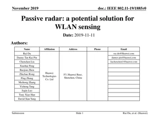
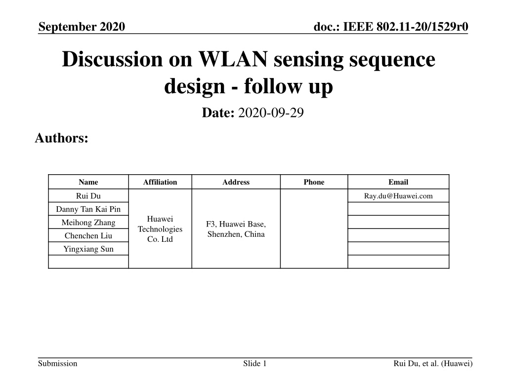
September 2020 doc.: IEEE 802.11-20/1529r0 Discussion on WLAN sensing sequence design - follow up Date: 2020-09-29 Authors: Name Affiliation Address Phone Email Rui Du Ray.du@Huawei.com Danny Tan Kai Pin Meihong Zhang Chenchen Liu Yingxiang Sun Huawei Technologies Co. Ltd F3, Huawei Base, Shenzhen, China Submission Slide 1 Rui Du, et al. (Huawei)
September 2020 doc.: IEEE 802.11-20/1529r0 Outline Abstract Ambiguity function Definition Analysis Two types of receivers R-D with correlation receiver R-D with match filter receiver Analysis of R-D map Analysis of R-D map with ambiguity function Metrics for range-Doppler map Comparison of ambiguity function and R-D map Summary References Submission Slide 2 Rui Du, et al. (Huawei)
September 2020 doc.: IEEE 802.11-20/1529r0 Abstract In previous presentations[1-2], the possibility of employing ambiguity function as a potential property for WLAN sensing sequence design is discussed. In this contribution, further analysis of ambiguity function and range-Doppler map is done and discussed. Submission Slide 3 Rui Du, et al. (Huawei)
September 2020 doc.: IEEE 802.11-20/1529r0 Definition of ambiguity function Ambiguity function is one of the most important/fundamental tools for radar waveform design and analysis. It is a two-dimensional function of time delay and Doppler shift, showing the output of the received signal through matched filter, and is defined as [3,4] ? ? ? ? ? ????????? ? ?= ? ?,?? Doppler Delay Submission Slide 4 Rui Du, et al. (Huawei)
September 2020 doc.: IEEE 802.11-20/1529r0 Analysis of ambiguity function As it is shown in the equation, ? is the propagation delay corresponding to the distance between the target and sensor, and ?? is the Doppler frequency introduced by target movement. The auto ambiguity function (AAF) shows the matched filter output of the signal/waveform. ? ? ? ? ? ????????? ? ?= ? ?,?? The cross ambiguity function (CAF) shows the mutual interference between different sequences in MIMO sensing scenario. ??? ?? Parameter estimation ? ? ? ????????? ?= ? ?,?? * Please note that cross ambiguity function also could be used for the description of match filter between transmitting signal and receiving signal. Submission Slide 5 Rui Du, et al. (Huawei)
September 2020 doc.: IEEE 802.11-20/1529r0 Two types of receivers Correlation receiver Cross correlation is done between the receiving signal (target echo) and transmitting signal (reference signal). Correlation peak appears at the time delay corresponding to the target distance. But, if the target is moving, a Doppler shift will be modulated into the echo signal. This induced Doppler shift will distort the output of the correlator where the correlation peak will no longer be optimal. It can be concluded that the Doppler information of the target cannot be detected with a single transmission using the correlation receiver (correlation only provide delay information). Matched filter receiver To compensate the Doppler shift introduced by the target movement, matched filter receiver could be employed. Matched filter will compensate the delay and Doppler to maximize the output energy (just as the ambiguity function s definition indicates) and the peak will appear at target s delay and Doppler shift. If the signal is long enough (having good Doppler resolution), it is able to detect the target distance and Doppler information simultaneously with a single transmission. Submission Slide 6 Rui Du, et al. (Huawei)
September 2020 doc.: IEEE 802.11-20/1529r0 R-D with correlation receiver Pulse 1 Pulse 2 Pulse 3 Pulse 4 PRI Pulse 1 Correlator Multi pulses/ Slow time Pulse 2 Doppler Pulse Ref Pulse 3 Doppler processing along slow time Pulse 4 Range Fast time/range To generate a range-Doppler map with correlation receiver, First, correlation is done for each pulse to generate a power delay profile (fast time). Then, Doppler processing is done along the slow time to get the range-Doppler map with 1. FFT, 2. High resolution algorithms, e.g. MUSIC amplitude information is lost because of the subspace method , etc. 3. Others. If the target is located at ? = 0,??= 0 (assume the receiving signal is exactly the same as the transmitting signal), the R-D map generated with correlation receiver is indicated by the ambiguity function of the transmitting signal. Submission Slide 7 Rui Du, et al. (Huawei)
September 2020 doc.: IEEE 802.11-20/1529r0 R-D with matched filter receiver Signal Signal Ref Match filter with f1 Match filter with f2 Doppler Match filter with f3 Match filter with f4 Delay/range If the matched filter receiver is adopted, Doppler shifts between the transmitting signal and receiving signal will be compensate, and the match filter peak will appear at the target delay and Doppler shift. If the pulse is long enough, we can get target s delay and Doppler information from the output of single pulse s matched filter. If the target is located in ? = 0,??= 0 (assume the receiving signal is exactly the same with the transmitting signal), the R-D map generated by matched filter receiver equals to the ambiguity function of the transmitting signal. Submission Slide 8 Rui Du, et al. (Huawei)
September 2020 doc.: IEEE 802.11-20/1529r0 Analysis of R-D map The 3dB mainlobe width along range is defined as the range resolution. range. the Doppler resolution. The maximum Doppler that could be detected is defined as the unambiguous Doppler frequency. The maximum detection range is defined as the unambiguous Doppler resolution Doppler region Doppler The 3dB mainlobe width along the Doppler dimension is defined as Range resolution Range Range Unambiguous range(????) Doppler resolution( ??) Unambiguous Doppler(??,??????) resolution( ?) ? ????=???? ? ??,??????= ??? ??? 2 1 1 R-D with correlation receiver ? = , ??= = 2? 2 2 ? ???? ???? ? ????=???? ? 1 R-D with matched filter receiver ??,??????= ?? ?? 2 ? = ??= 2, 2? 2 ???? ?is the signal bandwidth. ???? is the pulse repetition interval. ???? is the coherent processing time. ??? is the pulse repetition frequency. ?? is the sampling frequency. Submission Slide 9 Rui Du, et al. (Huawei)
September 2020 doc.: IEEE 802.11-20/1529r0 Analysis R-D map with ambiguity function Top view Doppler resolution Doppler Delay resolution Doppler Delay Delay For the R-D map generated with correlation receiver, each row of the R-D map is a cross correlation between transmitting signal and receiving signal. The correlation result with different Doppler shift (after Doppler processing) is indicated in ambiguity function. For the R-D map generated with the matched filter receiver, ambiguity function is the output of matched filter (this is clearly shown by the equation in slide 4) ! Both of the receivers outputs are indicated by the ambiguity function ! Correlation receiver is often adopted in pulse radar. It has equivalent performance but lower computation complexity. Submission Slide 10 Rui Du, et al. (Huawei)
September 2020 doc.: IEEE 802.11-20/1529r0 Metrics for range Doppler map Doppler processing Parameter estimation Performance analysis Range processing CFAR detector -5000 -5000 1 50 Range estimation. Doppler/speed estimation. Amplitude estimation. 100 -4000 -4000 100 0.9 0 50 200 -3000 -3000 0.8 -50 0 -2000 -2000 300 0.7 -100 -50 -1000 -1000 400 0.6 Doppler(Hz) Doppler(Hz) Slow time This is an example, CE is used for sensing PRF of pulse is 10 kHz Number of integration pulses is 1000 Carrier frequency is 60 GHz Bandwidth is 1.76 GHz Target parameter ? = 8?,? = 1?/? FFT is used for Doppler processing -150 500 0 0 0.5 -100 1000 1000 600 0.4 -200 -150 700 2000 2000 0.3 -250 -200 800 0.2 3000 3000 -300 -250 900 4000 4000 0.1 -350 -300 1000 0 0 5 10 15 0 5 10 15 0 5 Range(m)/Fast time 10 15 Range(m) Range(m) Due to the potential transmission approach of sequence in WLAN sensing, correlation receiver could be adopted and a simple simulation is shown above on. What metrics could be used for the evaluation of range Doppler map ? Peak to sidelobe ratio, et al. (already included in the ambiguity function) Estimation accuracies (range, speed accuracy) To estimate the range and Doppler/speed of the target, a detector should be adopted (CA-CFAR is adopted in this example). To evaluate the performance, end to end simulation is needed ! Slide 11 Submission Rui Du, et al. (Huawei)
September 2020 doc.: IEEE 802.11-20/1529r0 Comparison of ambiguity function and R-D map Ambiguity function It is a fundamental analysis of waveform which indicates the limitation and utility of the waveforms and provide a guideline for the selection of suitable waveforms for variable applications. It has been adopted for radar waveform design and analysis in the last few decades[3,4]. Range-Doppler map It gives the signal processing/sensing results within the coherent processing time and could be used for the evaluation of sensing performance in certain scenarios. Submission Slide 12 Rui Du, et al. (Huawei)
September 2020 doc.: IEEE 802.11-20/1529r0 Summary In this presentation, further analysis of ambiguity function is introduced and discussed. Based on the discussion above on, ambiguity function and R-D map both could be used for the evaluation of sensing, and ambiguity function is a more fundamental choice for the waveform design and analysis. Submission Slide 13 Rui Du, et al. (Huawei)
September 2020 doc.: IEEE 802.11-20/1529r0 References [1] 11-20-1328-00-SENS-discussion-on-wlan-sensing-sequence-design.pp tx [2] 11-20-1444-00-SENS-Golay Sequences and Ambiguity Function.pptx [3] Skolnik M I. Introduction to radar systems[M]. New York: McGraw-hi ll, 1980. [4] Mahafza B R. Radar systems analysis and design using MATLAB[M]. CRC press, 2002. Submission Slide 14 Rui Du, et al. (Huawei)
September 2020 doc.: IEEE 802.11-20/1529r0 Annex: sensing the slow moving target To sense the slow moving target, some approaches could be adopted, such as Increasing the carrier frequency Doppler frequency for monostatic sensing could be calculated with ??=2??????? ? ??????? is the radial velocity of target, ? is the wavelength corresponding to carrier frequency. Doppler shift ?? increases with the carrier frequency increases. Increasing the coherent processing time(CPI) Doppler resolution is defined with 1 ???? Doppler resolution ?? increases with the increase in CPI. ??= Submission Slide 15 Rui Du, et al. (Huawei)