Robotics Competition Journey: Team #6389 Lazybotts FTC Res-Q CAD Design Review
Follow Team #6389 Lazybotts from concept to competition as they share lessons learned, design strategies, and their iterative CAD design process in preparation for the RES-Q challenge. Discover insights on robot speed, scoring tactics, and autonomous capabilities, all aimed at achieving success in robotics competitions.

Download Presentation

Please find below an Image/Link to download the presentation.
The content on the website is provided AS IS for your information and personal use only. It may not be sold, licensed, or shared on other websites without obtaining consent from the author. Download presentation by click this link. If you encounter any issues during the download, it is possible that the publisher has removed the file from their server.
E N D
Presentation Transcript
1 Robots from concept to competition September 21, 2015 October 14, 2015 Team #6389 - Lazybotts FTC Res-Q CAD Design Review
Introduction 2 Who are we? Team #6389 - Lazybotts Eden Prairie, MN 4th year community team 9 team members ranging from 7th-10th grade lazybotts@gmail.com October 14, 2015
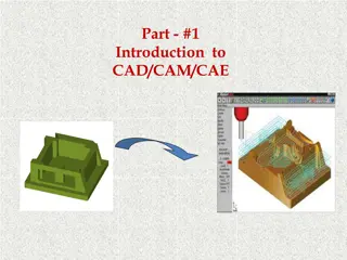
Overview 3 Today s talk will include: Lessons learned from Cascade Effect Our team s design goals for RES-Q CAD Iterative Design Process Design for Manufacturing Speed Shifting Gearbox Model Review in Creo Questions October 14, 2015
Lessons Learned 4 Lessons learned from Cascade Effect Speed of large ball collection and scoring made the difference Fast robots gained an advantage in being able to get to collect balls first Scoring in 120cm goal was important but eventually everyone could get these points World championship s floor was thick carpet instead of hard floor many heavy robots suffered in autonomous. October 14, 2015
RES-Q Design Strategy 5 Very fast robot on the floor Fast debris collection Focus on collecting blocks over balls Able to climb ramp at least to first churro Extend bucket on lift to dump into high goal Winch to pull up robot at end of game Reliable and repeatable autonomous scoring
CAD Iterative Design 6 We use an iterative CAD design process with different goals for each phase. Conceptual Phase Feasibility Phase Build Phase Presentation Phase
CAD Iterative Design 7 Conceptual Phase How can we make the design ideas work?
CAD Iterative Design 8 Feasibility Phase How do all the ideas work together? Does everything fit in the box? How much will it all weigh? Do we meet the game objectives? Do parts interfere when they move? Are purchased parts available?
CAD Iterative Design 9 Feasibility Phase
CAD Iterative Design 10 Build Phase How will these parts be manufactured? Is everything the right size?
CAD Iterative Design 11 Build Phase Is the design appropriate for the selected manufacturing technique? What parts need to be purchased?
CAD Iterative Design 12 Presentation Phase How can we best showcase our design?
Design for Manufacturing 13 Waterjet We use waterjet to cut inch aluminum plate
Design for Manufacturing 14 Waterjet Create a drawing at 1:1 scale and save as DXF
Design for Manufacturing 15 Waterjet Also create a drawing with dimensions and notes and save as PDF
Design for Manufacturing 16 Waterjet Research and understand the process.
Design for Manufacturing 17 3D Printing Both for prototypes and production parts
Design for Manufacturing 18 3D Printing Make plastic parts thicker and add gussets for strength
Design for Manufacturing 19 Machining CNC mills and lathes can make almost any part out of metal
Design for Manufacturing 20 Machining Some machine shops will use CAM software to produce parts directly from 3D models
Design for Manufacturing 21 Machining Some machine shops will program the CNC machines directly from the drawing Even if they accept 3D models, always provide the machine shop with a drawing including every dimension needed to reproduce the part.
Design for Manufacturing 22 Machining CNC machines can be very accurate and repeatable but it is important to learn what tolerances and features are really needed. .005 is about the thickness of a single piece of paper Holes or pockets more than 3-5 times the diameter can be difficult to do accurately (especially for diameters < )
Speed Shift Gearbox 23 Robot being fast and strong are competing design objectives ! Being able to shift between high and low gear allows having a robot that is faster in high gear and stronger in low gear than a single compromise solution could be. The trade off is added design complexity
Speed Shift Gearbox 24 FRC robots have used dual speed gearboxes for a long time. Some FTC teams have begun to have successful speed shift designs (Cougar Robotics 4251) FRC commonly use pneumatic shifters but we aren t allowed to (yet) so we will use servos.
Speed Shift Gearbox 25 Two main design options Dog Ear with Shifting Cog Ball Gear
Speed Shift Gearbox 26 Ball Gears have internal cutouts where free floating steel balls will engage the gear to the output shaft.
Speed Shift Gearbox 27 The output shaft has holes that retain the locking balls.
Speed Shift Gearbox 28 A shifting actuator controls which output gear is able to drive the output shaft
Speed Shift Gearbox 30 Three main components Cluster Shaft 50 Tooth Gear and 24 Tooth Gear on a common shaft Output Shaft 60 Tooth Ball Gear and 34 Tooth Ball Gear driving a Hex output shaft Speed Select Actuator Servo actuated to engage output shaft to cluster shaft at either the 60:24 or 34:50 gear ratio
Questions? 32 Website: www.lazybotts.com Email: lazybotts@gmail.com Twitter: @lazybotts Facebook: https://www.facebook.com/lazybotts October 14, 2015