Exploring Onshape: A Cloud-Based 3D CAD Package for Students
Onshape is a free cloud-based 3D CAD package perfect for students. It offers familiar features to Solidworks users, making it easy to transition. Learn how to sign up, access the interface, set preferences, and start your first 3D modeling project in this guide.
Download Presentation
Please find below an Image/Link to download the presentation.
The content on the website is provided AS IS for your information and personal use only. It may not be sold, licensed, or shared on other websites without obtaining consent from the author. Download presentation by click this link. If you encounter any issues during the download, it is possible that the publisher has removed the file from their server.

Presentation Transcript
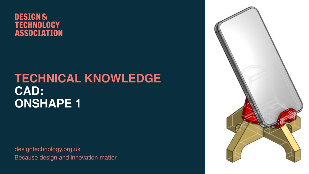
TECHNICAL KNOWLEDGE CAD: ONSHAPE 1 designtechnology.org.uk Because design and innovation matter
CONTENTS 1. Introduction to Onshape 2. The Onshape interface 3. Basic modelling
ONSHAPE Because design and innovation matter Because design and innovation matter
ONSHAPE Onshape is a 3D CAD package available free to students. It is a cloud-based app which means it does not require installing on a device. Because of this is can be accessed and used on Mac or PC, tablet and even your mobile phone. The software was developed by a team of experience software engineers, many of them worked on the development of Solidworks which is industry standard CAD software. This means that Onshape shares many functions and operations as Solidworks so anyone coming from that software would be familiar with the Onshape interface and vice versa. Onshape can even read parts made in Solidworks and parts exported from other software such as Fusion 360, CREO etc.
ONSHAPE In order to get access to your free educational Onshape account, you need to visit www.onshape.co/edu From the main page choose to sign up for a free account If you already have an account, choose to sign in
ONSHAPE Once you go through the sign-up process you will have an online account and you can then enter your email and password to sign in. In the next section we will look at the Onshape interface and the basic modelling tools. We will also set up the interface for our first 3D model.
INTERFACE Because design and innovation matter Because design and innovation matter
ONSHAPE INTERFACE When you first sign in to Onshape you will see a screen similar to the one below. If you have used Onshape before, you will see the projects you have been working on. Before we start there are a few things we need to set up as they will be harder to change later. Click on your account name in the top right and choose My account
ONSHAPE INTERFACE In the account screen, choose preferences from the left-hand menu. It is advisable to change all of the units to decimal so ensure you have the Length units set to Millimeter and Mass units to Kilogram before starting any project. Once you have done this be sure to click Save changes or your units will remain at their default settings which is usually Inches.
ONSHAPE INTERFACE You can also set up shortcuts, mouse controls and other settings but it is best to leave most of these as they are until you become more experienced at using the software. Just check your units are Millimeters before proceeding. Then click on the Onshape logo to return to your documents. If it is your first time using the software, there will be no projects there so let s start making one.
ONSHAPE INTERFACE Click on the Create button to make your first part. You will have the choice to create a Document or a Folder. If you plan on creating many parts for your project and want to keep them organized, you can create a Folder and then documents to place in it. For the purpose of this tutorial, because we are making just a few parts, we will start by making a document.
ONSHAPE INTERFACE You will then be taken to the Onshape interface. It is worth taking some time to familiarize yourself with the tools and functions in there.
ONSHAPE INTERFACE This is the toolbar where all the modelling and sketching tools can be found This is the modelling area where you can see the three planes This is the feature tree where you can see your sketches and processes as you progress This cube shows the views. You click on a face to select that view or rotate it. These are the tabs where you can see the parts and assemblies you are working on
BASIC MODELLING Because design and innovation matter Because design and innovation matter
BASIC MODELLING The main screen shows the three main planes you can view or sketch on. They are Front, Right and Top. If you click on the Top Plane, it will be highlighted in orange. If we Right Click on it a menu will pop up and we can choose New sketch. Here you can see the planes in the feature tree. Visibility can be toggled on and off with the eye icon.
BASIC MODELLING A good tip, once you select a plane or face to draw on, is to choose to view normal to . This means to look directly at that face or plane. Once a plane or face is selected, you can press n on the keyboard. In this case it will change your view to look directly at the Top plane.
BASIC MODELLING You will now enter sketch mode and the toolbar will change to show the sketch tools. Notice how the toolbars change depending on what process or function you have chosen. Choose the arrow next to the rectangle tool to see other options from a drop-down menu. For this tutorial we will be using the Center point rectangle. Clicking on the plane you can drag a rectangle out from the centre point BUT we want to make sure that we start our sketch from the origin point.
BASIC MODELLING At the point where all the planes intersect, you will see a small circle or dot. This is the origin point. It is important that whatever you model starts here or is referenced to this point through a measurement etc. Click on the point and drag to make a square shape. Don t worry if it s not accurate. Click to form the shape but then type 50, press TAB and type 50 again. This dimensions each side of the square as 50mm. If you forget to dimension you can press d on your keyboard or choose the dimension icon from the toolbar.
BASIC MODELLING We now have our first sketch which is automatically named Sketch 1, but it is a good idea to change the names of sketches and process to something more recognisable, especially as the project becomes more detailed and complex. To do this, R-click on Sketch1 and choose Rename . You can now type in a different name. Let s call this SquareBase . You should now see a set of tools like this in the toolbar. We are going to Extrude the shape to make it 3D. Click on this icon
BASIC MODELLING By default, extrude will make a new solid part and be set to Blind, which means it simply extrudes in one direction by the distance you choose. You can also drag the arrow on the 3D model, but this can be less accurate. Because we want the planes to be in the centre of the cube, we will choose Symmetric option and type 50mm. This will extrude the square 25mm each side of the plane.
BASIC MODELLING We now have a cube with all the planes intersecting in the very centre of the cube. Working like this makes it easier to revolve features around the cube or to mirror them. As an example, we can choose a feature on the top surface, select the top plane as the mirror surface and the feature will be mirrored to the bottom of the cube. Features here Can also be mirrored here
BASIC MODELLING You now have a basic cube. It is the correct dimensions and in the very centre of the work area. The cube looks very plain and square so we next to add some detail to the edges. We could use a Chamfer or Fillet. The Chamfer tool (next to the Fillet) puts a flat slope between two edges, but we want rounded edges so choose the Fillet tool.
BASIC MODELLING Once the Fillet tool is selected you can select each edge separately but, as we want all edges filleting, you can select the whole part and add a 9mm fillet.
BASIC MODELLING You have now modelled a 50mm cube which rounded edges. Review your progress so far and practice the tools and processes used.