Discussion on Isolating Flanges in SPS Impedance Model
Discussing the installation and impact of insulating flanges in the SPS, particularly on eddy currents and resonance effects. The presence of isolated flanges to prevent eddy currents in grounding loops is analyzed, along with potential enhancements in dynamic effects. Preliminary measurements and motivations for using insulating flanges are highlighted, focusing on the avoidance of resonances and impedance issues.

Download Presentation

Please find below an Image/Link to download the presentation.
The content on the website is provided AS IS for your information and personal use only. It may not be sold, licensed, or shared on other websites without obtaining consent from the author. Download presentation by click this link. If you encounter any issues during the download, it is possible that the publisher has removed the file from their server.
E N D
Presentation Transcript
Summary of discussion on isolating flanges E. Shaposhnikova With input from LIU-SPS BD WG (in particular H. Bartosik, F. Caspers and J. Varela), K. Cornelis, B. Goddard , BI colleagues (C. Boccard, ) LIU-SPS BD WG meeting 21.05.2015
Outline SPS impedance model (reminder) What do we understand What do we need to study
Present SPS longitudinal impedance model Model includes: 200 MHz cavities (2+2) 628 MHz HOM 800 MHz cavities (2) Kicker magnets (8 MKEs, 4 MKPs, 5 MKDs, 2 MKQs) Vacuum flanges (~500) + DR BPMs: BPH&BPV (~200) Unshielded pumping ports (~ 16 similar + 24 various) - non-conformal assumed 0 Y chambers (2 COLDEX + 1) Beam scrappers (3 S + 4 UA9) Resistive wall AEPs (RF phase PUs, 2) ~ 0 Model doesn t include: 6 ZSs + PMs 25 MSE/MST + PMs HOMs 200 MHz & 800 MHz RF RF VF Scrap. VF HOM BPM Y-c EM simulations of J. Varela & C. Zannini + Lab measurements for 200 MHz, PPs, VFs (J. Varela et al.)
The SPS vacuum flanges Group I 1.4 GHz Non-enamelled QF - QF 26 Enamelled QF - MBA 97 Non-shielded, enamelled BPH - QF 39 + 64 shielded Group II Enamelled QD - QD 99 Enamelled BPV - Q 90 Non-enamelled QD - QD 75
The SPS vacuum flanges Scattered resonances, J. Varela
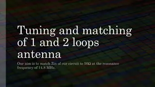
Insulating (Enamel) flanges in the SPS: motivation The impact of eddy currents on the beam is seen in chromaticity variation along the ramp and its decay at the injection plateau. However it is not clear if this effect is mainly connected to eddy currents in beam pipes or in grounding loops Insulating flanges were installed to avoid eddy-current in the loops formed by grounding cables (one at each last dipole in cell) If existing insulated flanges are short-circuited, the dynamic effect of eddy currents could be enhanced due to grounding loops Checks during LS1 (OP, VAC, RF) show that new layouts often don t have information about isolation flanges and groundings (as well as for damping resistors) and don t correspond to reality Isolating flange together with grounding loop forms a resonator (PS: fres 1.5 MHz, Q 1, n 200 - a huge source of PS impedance cured by RF by-pass). Preliminary measurements were also done in the SPS (F. Caspers, 2013): fres ~ 25 MHz (?), impedance not known
Isolating flanges around BPMs VF BPM grounding cable
Insulating (Enamel) flanges in the SPS ~389 enamelled PUs around each BPM 64 from them are short-circuited due to impedance shielding (similar to pumping ports); 39 of the same type are not shielded BI didn t see any negative effects of short-circuits future BPM MOPOS system will use transformers (&optic link) ~23 RF PUs with enamelled flanges on both sides. These PUs are grounded via coaxial cables going to BA3 (FC). A few of them had isolation problems (T. Bohl) 6 PUs used for transverse damper (W. Hofle) insulation is under investigation There are others devices, mainly in LSSs (individual equipment) not in the list for impedance reduction
Possible actions/studies An experimental check of the effect of ground loops on the new MOPOS electronics could be done with the BPMs used for the transverse damper, which are already equipped with the new electronics, by short-circuiting the adjacent Enamel flanges The eddy currents in ground loops induced by the variation of the magnetic field and the resulting multipole components seen by the beam could be simulated (?) A test could be done by short-circuiting a large number of Enamel flanges (?). One can question present SPS groundings and study their improvements (F. Caspers) > ideas for different tests in lab and tunnel
Summary Isolated flanges should be preserved where they are already installed unless another equivalent solution is implemented via grounding cables (as for new MOPOS system or transverse damper - tbc) Existing shielding of isolating flanges is not necessary should be removed if another isolating flange is kept and then grounding loop is avoided by other means Type of shielding of existing isolating flanges near BPM could be decided after some additional tests Cleaning of the SPS ring (layouts, grounding loops, isolation) could help for future operation and diagnostics
Impedance of vacuum flanges Element Q R/Q [ ] Enam Res. * Num. f [GHz] Z [k ] Yes No 1.210 633 315 2010 90 Flanges [ Simulation Table ] Yes Long 1.280 499 200 !! 2495 39 Yes Short 1.415** 364 75 ** 4856** 5% 90% of 83 ! * Damping Resistors have not been included in Simulations. This column states whether or not the flange SHOULD have a damping resistor inside (and its type). Yes No 1.415** 177 270 ** 656** 5% 10% of 83 ! Yes Short 1.415m 61.4 75 819 5% 90% of 14 ! Yes No 1.415m 29.9 270 110 5% 10% of 14 ! ** The enamelled QF-MBA case is assumed to be identical to the measured enamelled MBA- MBA flange. Should be very close in reality. No Short 1.395m 379 200 1895 2.5% 90% of 26 *** No No 1.401m 243 1100 221 2.5% 10% of 26 *** *** Survey by Jose A. Ferreira (18/26 flanges surveyed). Yes No 1.570 17.4 55 316 99 ! Damping resistor presence percentage is assumed to be identical to the *** case. No No 1.610 588 980 600 20 Yes Long 1.620 61 60 !! 1016 39 !! The effect of the LONG damping resistors has not been estimated. In this table, it is assumed to be identical to a SHORT damping resistor. No Yes 1.861 771 810 952 75 Yes No 1.890 187 175 1070 99 m Indicated entries that have been measured in the lab. No Yes 2.495 814 1190 685 75 data from J. Varela


 flanges in the SPS:")

 flanges in the SPS")