Overview of ICARUS LAr-TPC Installation and Testing
Detailed overview of the installation and testing procedures for the ICARUS Liquid Argon Time Projection Chamber (LAr-TPC) readout electronics. The system comprises front-end amplifiers, ADC systems, optical links for data transmission, mini-crates housing the electronics boards, power supplies, and signal distributions. The installation involved equipping flanges with boards, setting up mini-crates, connecting A2795 boards, testing power supplies, and preparing for vertical slice tests.

Download Presentation

Please find below an Image/Link to download the presentation.
The content on the website is provided AS IS for your information and personal use only. It may not be sold, licensed, or shared on other websites without obtaining consent from the author. Download presentation by click this link. If you encounter any issues during the download, it is possible that the publisher has removed the file from their server.
E N D
Presentation Transcript
H2020, M. Sklodowska-Curie R&I No. 822185 INTENSE Overview on the installation and tests of the ICARUS LAr-TPC readout electronics 1.ICARUS TPC Read-out System Overview 2.TPC electronics installation 3.Vertical slice tests C. Farnese & A. Guglielmi for the INTENSE WP 1 Great results in the installation and tests of the ICARUS of ICARUS LAr-TPC electronics provided by the collaboration with FNAL colleagues, possible thanks to INTENSE INTENSE General Meeting November 6th2019
ICARUS TPC Read-out System Overview The new warm ICARUS TPC electronics includes: A front-end based on analogue low noise/charge sensitive pre-amplifier - same for Induction/Collection wires; A serial 12 bit ADC system, one per channel with 400 ns sync. sampling; A serial bus architecture with optical links for Gigabit/s transmission. Both analogue/digital electronics hosted in a single board directly mounted on a signal feedthrough flange. External side of flange acts as backplane for a custom mini-crate where 9 boards (576 ch) are housed: 64 pre-Amps/ADC per board, 0-3.3V rail to rail, FPGA, optical link Backplanes of mini-crates distribute power supply/local control signals Wire signals decoupled from HV bias by DBB boards installed in the internal side of flanges. Backplane connector H.V. (< 500 V) REG REG Trigger Liquid argon Gas TT-link Sense wires (4-9m, 20pF/m) Twisted pair cables (~1.8-6.2 m, 50pF/m) ADC Fibers FPGA cal opti link Induction (32ch) ADC Test IN RAM Collection (32ch) UHV Feed-through (18x32ch) Decoupling board 12bit serial ADC 400ns sampling JINST 13 (2018) P12007 Front-end ampl (64/board) Slide# : 2
TPC electronics installation - 1 All the 96 flanges with DBBs, Mini-crates, 838 over 856 required A2795 CAEN boards equipped with their pre-Amps, power supplies already installed DAQ read-out based on CAEN A3818 optical links: TPC + PMT signals read by 24 + 3 PCs, each hosting 2 CAEN A3818 boards. 3 PCs more are reserved for CRT data reading. All required 54 + 6 spare A3818 boards delivered by CAEN already at FNAL. All 30 + 5 spare PCI-express HP Proliant DL 380 delivered at CERN: first 6 PCIs already at FNAL, the remaining 29 on their road. Procurement of the associated connecting fibers is ongoing TT-Link (LVDS signals), which carries all relevant infos for DAQ generated by the central trigger crate, will be distributed to all 96 Mini- crates by some 6+2 spare fan-out units (1 input, 26 outputs) prepared by CSU team Slide# : 3
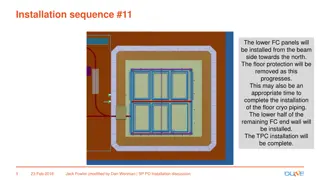
TPC electronics installation - 2 Two mini-crates with 9 A2795 boards on two chimneys for Induction 2 and Collection wires connected to power supplies Three mini-crates with 9 A2795 boards on one corner chimney: 3 vertical flanges for horizontal (Induction 1) and short wires on TPC corner, connected to power supplies. TOP MIDDLE BOTTOM HV distributor 2 power supplies All power supplies have been tested with 9 boards load Slide# : 4
Vertical Slice test: 72 standard chimneys Full TPC vertical slice tests performed on all the 72 standard chimneys associated to 3.8 m long Collection/Induction2 wires to evaluate the overall performance; events has been collected with random trigger and injecting test pulses at the far end of chamber wires and reading out the signals by A2795 The new power supply modules properly connected; A server with one A3818 board used to receive data through optical links. Typical baseline noise, test pulse shape (board 1, ch 27, EE16) RMS: 3 #ADC. Globally 41472 channels (648 boards) studied: all channels behave as expected with ~3 #ADC (~1640 e-) noise level: Only ~ 0.2 % of chs requires additional checks (changing pre-Amps or repairing boards if required. RMS noise (#ADC) Slide# : 5
Vertical Slice test: 24 flanges on 8 corner chimneys Similar TPC vertical slice tests were performed on the 24 corner flanges which refer to 12800 chs horizontal 9 m long Induction1 wires, shortest Induction 2 and Collection wires in the corners; TP height (#ADC) RMS (#ADC) channel channel Globally 12800 channels (208 boards) studied: identified 0.4% single channels that should be cured changing pre-Amps or repairing boards: The average noise level, in particular on Middle and Top crates, is ~ 5#ADC, a bit higher w.r.t. expectations, due to the presence of an higher correlated noise. Middle crates, Induction1 wires Bottom crates, Induction2/ Collection wires Top crates, Induction1 wires RMS (#ADC) RMS (#ADC) RMS (#ADC) Slide# : 6