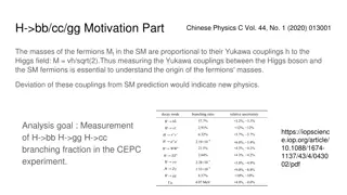
Analysis of Bunch Lengthening in CEPC for Different Design Parameters
This study explores bunch lengthening in the Circular Electron Positron Collider (CEPC) for various design parameters, analyzing a 54 km design scheme, a 61 km design scheme, and a 100 km design scheme. The analysis includes the theoretical framework used, equations for bunch lengthening, and conclusions drawn from the study. Additionally, parameters for the CEPC partial double ring are detailed along with an impedance budget based on the 54 km design scheme, highlighting the components contributing to coupling impedance dominated by resistive wall impedance.

Download Presentation

Please find below an Image/Link to download the presentation.
The content on the website is provided AS IS for your information and personal use only. It may not be sold, licensed, or shared on other websites without obtaining consent from the author. Download presentation by click this link. If you encounter any issues during the download, it is possible that the publisher has removed the file from their server.
E N D
Presentation Transcript
Bunch Lengthening in CEPC for Different Design Parameters Hongjuan Zheng, Jie Gao, Na Wang 2017-01-13
Outline Bunch lengthening analysis 54 km design scheme 61 km design scheme 100 km design scheme Conclusion 2
Bunch lengthening analysis Theory used The bunch lengthening equation is as follows: 2 2 ( ) ( ( R ) ) I R Rk I R Rk = + + 2 z 1 0 0 2 R av z b av z b 3.5 7 ( ) ( ) R z z = / R 0 z z z Energy spread is: 2 ( ( R ) ) I R Rk = + 2 1 0 2 av z b R 7 ( ) z = / R 0 z z [1] J. Gao, On the single bunch longitudinal collective effects in electron storage rings, Nuclear Instruments and Methods in Physics Research A 491(2002) 1-8. [2] J. Gao, An empirical equation for bunch lengthening in electron storage ring, Nuclear Instruments and Methods in Physics Research A 432 (1999) 539-543. 3
Parameters for CEPC partial double ring wangdou20160325 Pre-CDR H-high lumi. H-low power W Z Number of IPs Energy (GeV) Circumference (km) SR loss/turn (GeV) Half crossing angle (mrad) Piwinski angle Ne/bunch (1011) Bunch number Beam current (mA) SR power /beam (MW) Bending radius (km) Momentum compaction (10-5) IP x/y (m) Emittance x/y (nm) Transverse IP (um) x/IP y/IP VRF (GV) f RF (MHz) Nature z (mm) Total z (mm) HOM power/cavity (kw) Energy spread (%) Energy acceptance (%) Energy acceptance by RF (%) n Life time due to beamstrahlung_cal (minute) F (hour glass) Lmax/IP (1034cm-2s-1) 2 2 2 2 2 120 54 3.1 0 0 3.79 50 16.6 51.7 6.1 3.4 120 54 2.96 15 2.5 2.85 67 16.9 50 6.2 2.5 120 54 2.96 15 2.6 2.67 44 10.5 31.2 6.2 2.2 80 54 0.59 15 5 0.74 400 26.2 15.6 6.1 2.4 45.5 54 0.062 15 7.6 0.46 1100 45.4 2.8 6.1 3.5 0.1/0.001 0.62/0.0028 7.9/0.053 0.006 0.073 0.12 650 3.9 4.0 0.99 0.05 0.8/0.0012 6.12/0.018 69.97/0.15 0.118 0.083 6.87 650 2.14 2.65 3.6 0.13 2 6 0.23 47 0.25/0.00136 2.45/0.0074 24.8/0.1 0.03 0.11 3.62 650 3.1 4.1 2.2 0.13 2 2.2 0.47 36 0.268 /0.00124 2.06 /0.0062 23.5/0.088 0.032 0.11 3.53 650 3.0 4.0 1.3 0.13 2 2.1 0.47 32 0.1/0.001 1.02/0.003 10.1/0.056 0.008 0.074 0.81 650 3.25 3.35 0.99 0.09 1.7 0.3 1.1 0.24 4 0.68 2.04 0.82 2.96 0.81 2.01 0.92 3.09 0.95 3.09
Impedance budget Impedance budget (from Na Wang, based 54 km design scheme) Coupling impedance dominated by Resistive wall impedance Vacuum elements with large numbers (RF cavities, flanges, BPMs, bellows, ) Vacuum elements with large impedances (IP duct, collimators, kickers, ) R, k L, nH Z||/n, m kloss, V/pC Components Number Resistive wall - 6.7 487.7 17.0 138.4 RF cavities 384 14.9 -132.7 - 307.5 Flanges ~10000 0.7 165.5 5.8 15.1 BPMs 2300 0.6 21.4 0.7 11.6 Bellows ~10000 5.9 331.5 11.6 122.3 Pumping ports ~10000 0.007 3.1 0.1 0.1 Total( =4.1mm) 28.8 876.5 35.2 595.0 5
54 km design scheme Bunch lengthening for different design Pre-CDR H-HL H-LP W Z 50 16.6 67 16.9 44 10.5 400 26.2 1100 45.4 Bunch number Beam current (mA) 51.7 50 31.2 15.6 2.8 SR power /beam (MW) VRF (GV) fRF (MHz) Total z (mm) Cavity no. loss factor (V/pC) inductance (nH) Rz R 6.87 650 2.65 384 1636.6 699 1.816 1.39 3.62 650 4.1 384 595 876.5 1.311 1.076 3.53 650 4 384 613.05 876.5 1.305 1.073 0.81 650 3.35 384 759.8 876.5 1.396 1.116 0.12 650 4 384 613.05 876.5 2.007 1.54 6
54 km design scheme Bunch lengthening for Higgs low power design Total wake potential of the ring 700 3.0 Rz R 456.25 2.8 2.6 212.5 2.4 31.25 2.2 W(z)/V/pC 2.0 RzR 275 1.8 1.6 518.75 1.4 762.5 1.2 1.0 )2 2 CC gamma3.5Rz1.21 0.5 CC Rav Rb ( gamma7Rz2.42 1.5 2.0 Ib (mA) 1006.25 Rav Rb K Ib Ib K root Rz2 Rz = 1 2.768 0.8 0.0 1.0 2.5 3.0 1250 0.04 0.02 0 0.02 0.04 z(m) With =4 mm, bunch current = 0.239 mA bunch lengthening is 30.5% energy spread is 7.3% 7
Parameters for CEPC partial double ring wangdou20160918/23 Pre-CDR 2 120 54 3.1 0 0 3.79 50 16.6 51.7 6.1 3.4 0.8/0.0012 6.12/0.018 69.97/0.15 0.118 0.083 6.87 650 2.14 2.65 3.6 0.13 2 6 0.23 47 H-high lumi. 2 120 61 2.96 15 1.88 2.0 107 16.9 50 6.2 1.48 0.272/0.0013 2.05/0.0062 23.7/0.09 0.041 0.11 3.48 650 2.7 2.95 0.74 0.13 2 2.3 0.35 37 H-low power 2 120 61 2.96 15 1.84 1.98 70 11.0 32.5 6.2 1.48 0.275 /0.0013 2.05 /0.0062 23.7/0.09 0.042 0.11 3.51 650 2.7 2.9 0.48 0.13 2 2.4 0.34 37 W 2 80 61 0.58 15 5.2 1.16 400 36.5 21.3 6.2 1.44 Z 2 Number of IPs Energy (GeV) Circumference (km) SR loss/turn (GeV) Half crossing angle (mrad) Piwinski angle Ne/bunch (1011) Bunch number Beam current (mA) SR power /beam (MW) Bending radius (km) Momentum compaction (10-5) IP x/y (m) Emittance x/y (nm) Transverse IP (um) x/IP y/IP VRF (GV) f RF (MHz) Nature z (mm) Total z (mm) HOM power/cavity (kw) Energy spread (%) Energy acceptance (%) Energy acceptance by RF (%) n Life time due to beamstrahlung_cal (minute) F (hour glass) Lmax/IP (1034cm-2s-1) 45.5 61 0.061 15 6.4 0.78 1100 67.6 4.1 6.2 2.9 0.1/0.001 0.88/0.008 9.4/0.089 0.01 0.072 0.11 650 3.78 4.0 0.99 0.05 0.1/0.001 0.93/0.0078 9.7/0.088 0.013 0.073 0.74 650 2.95 3.35 0.88 0.087 1.7 0.49 1.2 0.34 0.68 2.04 0.82 3.1 0.82 2.01 0.92 4.3 0.93 4.48 8
61 km design scheme Bunch lengthening for different design H-HL H-LP W Z 107 16.9 70 11.0 400 36.5 1000 67.6 Bunch number Beam current (mA) 50 32.5 21.3 4.1 SR power /beam (MW) 3.48 650 2.95 384 886.14 876.5 1.325 1.082 3.51 650 2.9 384 904.66 876.5 1.329 1.084 0.74 650 3.35 384 759.77 876.5 1.566 1.215 0.11 650 4.0 384 613.05 876.5 2.414 1.888 VRF (GV) fRF (MHz) Total z (mm) Cavity no. loss factor (V/pC) inductance (nH) Rz R 9
61 km design scheme Bunch lengthening for Higgs low power design Total wake potential of the ring 1250 Rz R 906.25 3.5 562.5 3.0 218.75 W(z)/V/pC 2.5 RzR 125 2.0 468.75 1.5 812.5 1.0 1156.25 0.0 0.5 1.0 1.5 2.0 2.5 3.0 Ib (mA) 1500 0.02 0.01 0 0.01 0.02 z(m) With =2.9 mm, bunch current = 0.157 mA bunch lengthening is 32.9% energy spread is 8.4% 10
Parameters for CEPC double ring wangdou20161219 Pre-CDR tt H-high lumi. H-low power W Z Number of IPs Energy (GeV) Circumference (km) SR loss/turn (GeV) Half crossing angle (mrad) Piwinski angle Ne/bunch (1011) Bunch number Beam current (mA) SR power /beam (MW) Bending radius (km) Momentum compaction (10-5) IP x/y (m) Emittance x/y (nm) Transverse IP (um) x/ y/IP RF Phase (degree) VRF (GV) f RF (MHz) (harmonic) Nature z (mm) Total z (mm) HOM power/cavity (kw) Energy spread (%) Energy acceptance (%) Energy acceptance by RF (%) n Life time due to beamstrahlung_cal (minute) F (hour glass) Lmax/IP (1034cm-2s-1) 2 2 2 2 2 2 2 120 54 3.1 0 0 3.79 50 16.6 51.7 6.1 3.4 120 100 1.67 15 2.9 0.97 644 29.97 50 11 1.3 120 100 1.67 15 2.9 0.97 425 19.8 33 11 1.3 80 100 0.33 15 3.57 1.05 1000 50.6 16.7 11 3.1 45.5 100 0.034 15 5.69 0.46 10520 232.1 8.0 11 3.3 0.12/0.001 0.93/0.0049 10.5/0.07 0.0075/0.054 160.8 0.11 45.5 100 0.034 15 5.69 0.46 65716 1449.7 50 11 3.3 0.12/0.001 0.93/0.0049 10.5/0.07 0.0075/0.054 160.8 0.11 175 100 7.55 15 1.6 1.41 98 6.64 50 11 1.3 0.8/0.0012 6.12/0.018 69.97/0.15 0.118/0.083 153.0 6.87 650 2.14 2.65 3.6 (5cell) 0.13 2 0.2/0.002 3.19/0.0097 25.3/0.14 0.016/0.055 122.2 8.92 650 2.62 2.7 0.53(5cell) 0.14 2 0.144 /0.002 1.56/0.0047 15/0.097 0.0126/0.083 131.2 2.22 650 (217800) 2.72 2.9 0.64 (2cell) 0.098 1.5 0.144 /0.002 1.56/0.0047 15/0.097 0.0126/0.083 131.2 2.22 650 (217800) 2.72 2.9 0.42 (2cell) 0.098 1.5 0.1 /0.001 2.68/0.008 16.4/0.09 0.0082/0.055 149 0.63 650 (217800) 3.8 3.9 1.0 (2cell) 0.065 650 (217800) 3.93 4.0 1.0 (1cell) 0.037 3.93 4.0 6.25(1cell) 0.037 2.2 0.26 52 2.2 0.26 52 1.5 0.26 1.1 0.18 1.1 0.18 6 2.6 0.23 50 0.23 47 11 0.68 2.04 0.95 3.1 0.95 2.05 0.84 4.08 0.91 11.36 0.91 70.97 0.89 0.62
Impedance budget Impedance budget (from Na Wang, based 100 km design scheme) Coupling impedance dominated by Resistive wall impedance Vacuum elements with large numbers (RF cavities, flanges, BPMs, bellows, ) Vacuum elements with large impedances (IP duct, collimators, kickers, ) R, k L, nH Z||/n, m kloss, V/pC Components Number Resistive wall - 15.7 863.1 16.3 458 RF cavities 384 12.6 -79.1 -1.5 366.7 Flanges ~18500 5.2 310.4 5.8 151.6 BPMs 4300 1.5 30.4 0.6 42.6 Bellows ~18500 17.7 375.1 7.1 515.6 Pumping ports ~18500 0.02 5.3 0.1 0.7 Total( =2.9mm) 52.7 1505.2 28.4 1535.2 12
100 km design scheme Bunch lengthening for different design H-HL H-LP W Z 644 29.97 425 19.8 1000 50.6 10520 232.1 65716 1449.7 65716 1449.7 Bunch number Beam current (mA) SR power /beam (MW) VRF (GV) fRF (MHz) Total z (mm) Cavity no. loss factor (V/pC) 50 33 16.7 8.0 50 50 2.22 650 2.9 384 1535.2 2.22 650 2.9 240 0.63 650 3.9 128 901.88 0.11 650 4.0 16 802.194 1581.00 4 2.707 2.152 0.11 650 4.0 64 812.548 1577.70 8 2.719 2.164 0.11 650 4.0 384 1040.4 1397.688 1505.2 1534.862 1557.93 1505.2 inductance (nH) Rz R 1.444 1.142 1.413 1.126 1.894 1.45 2.986 2.411 13
100 km design scheme Bunch lengthening for Higgs low power design Total wake potential of the ring 1700 5.0 Rz R 1212.5 4.5 4.0 725 3.5 237.5 W(z)/V/pC RzR 3.0 250 2.5 737.5 2.0 1225 1.5 1.0 1712.5 )2 1.50 2 CC gamma3.5Rz1.21 CC Rav Rb ( gamma7Rz2.42 Rav 0.25 Rb K Ib Ib K 0.00 0.50 0.75 1.00 1.25 1.75 2.00 root Rz2 Rz = 1 1.413 Ib (mA) 2200 0.02 0.01 0 0.01 0.02 z(m) With =2.9 mm, bunch current = 0.047 mA bunch lengthening is 41.3% energy spread is 12.6% 14
Conclusion The estimated results show that the bunch lengthening is a problem in CEPC, especially for Z design. The resistive wall and the bellows contribute more than half total loss factors and total inductance for the 100 km design. The proportion of cavity loss factors decrease for the 100 km design. 15