Understanding OSI Model and TCP/IP Protocol Suite in Computer Networking
This content delves into the OSI model and TCP/IP protocol suite, highlighting the protocol layers, addressing mechanisms, and communication scenarios. It explores the functions of each layer, the interface between layers, and compares the TCP/IP layers with the OSI model. Through examples and illustrations, the importance of protocol layering and communication in networking is explained.

Download Presentation

Please find below an Image/Link to download the presentation.
The content on the website is provided AS IS for your information and personal use only. It may not be sold, licensed, or shared on other websites without obtaining consent from the author. Download presentation by click this link. If you encounter any issues during the download, it is possible that the publisher has removed the file from their server.
E N D
Presentation Transcript
The OSI Model and the TCP/IP Protocol Suite Outline: 1. Protocol Layers 2. OSI Model 3. TCP/IP Model 4. Addressing
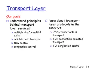
OBJECTIVES To discuss the OSI model and its layer architecture and to show the interface between the layers. To briefly discuss the functions of each layer in the OSI model. To introduce the TCP/IP protocol suite and compare its layers with the ones in the OSI model. To show the functionality of each layer in the TCP/IP protocol with some examples. To discuss the addressing mechanism used in some layers of the TCP/IP protocol suite for the delivery of a message from the source to the destination. TCP/IP Protocol Suite 2
Computer Network Components Components of a computer network: Computer with NIC (PCs, laptops, handhelds) routers & switches (IP router, Ethernet switch) Links Transmission media (wired, wireless) protocols (IP,TCP,CSMA/CD,CSMA/CA) applications (network services) i.e. Network Operating System (NOS) humans and service agents 3 10/8/2024 Fatimah AlAkeel - Network 1
PROTOCOL LAYERS we discussed that a protocol is required when two entities need to communicate. When communication is not simple, we may divide the complex task of communication into several layers. The sending computer must: Recognize the data. Divide the data into manageable chunks. Add information to each chunk of data to determine the location of the data and to identify the receiver. Add timing and error-checking information. Put the data on the network and send it on its way. In this case, we may need several protocols, one for each layer. TCP/IP Protocol Suite 4
PROTOCOL LAYERS Let communication in which the role of protocol layering may be better understood. We use two examples. In the first example, communication is so simple that it can occur in only one layer. us use a scenario in
Example 1 Assume Maria and Ann are neighbors with a lot of common ideas. However, Maria speaks only Spanish, and Ann speaks only English. Since both have learned the sign language in their childhood, they enjoy meeting in a cafe a couple of days per week and exchange their ideas using signs. Occasionally, they also use a bilingual dictionary. Communication is face to face and Happens in one layer as shown in Figure. TCP/IP Protocol Suite 6
Example 2 Now assume that Ann has to move to another town because of her job. Before she moves, the two meet for the last time in the same cafe. Although both are sad, Maria surprises Ann when she opens a packet that contains two small machines. The first machine can scan and transform a letter in English to a secret code or vice versa. The other machine can scan and translate a letter in Spanish to the same secret code or vice versa. Ann takes the first machine; Maria keeps the second one. The two friends can still communicate using the secret code, as shown in Figure. TCP/IP Protocol Suite 7
THE OSI MODEL Established in 1947, the International Standards Organization (ISO) is a multinational body worldwide agreement on international standards standards. Almost three-fourths of countries in the world are represented in the ISO. An ISO standard that covers all aspects of network communications is the Open Systems Interconnection (OSI) model. It was first introduced in the late 1970s. dedicated international to TCP/IP Protocol Suite 8
Topics Discussed in the Section Layered Architecture Layer-to-layer Communication Encapsulation Layers in the OSI Model TCP/IP Protocol Suite 9
Note ISO is the organization; OSI is the model. TCP/IP Protocol Suite 10
OSI Model and Nora 7th floor Nora gets secret message from Number One Application 6th floor Message is translated, encrypted and miniaturized Presentation 5th floor Security checks message, adds checkpoints to ensure the embassy receives whole message Session 4th floor Message is analysed, combined if necessary and broken into smaller pieces Transport 3rd floor Personnel check the message, determine the address, indicate fastest route to Embassy Network 2nd floor Message placed in special packet contains message, sender and destination ID Data Link 1st floor Prepared for a trip to the KSA Embassy Physical
OSI layers TCP/IP Protocol Suite 12
An exchange using the OSI model ( Encapsulation) TCP/IP Protocol Suite 13
Note The physical layer is responsible for moving individual bits from one (node) to the next. TCP/IP Protocol Suite 14
Summary of OSI Layers TCP/IP Protocol Suite 15
TCP/IP Model The protocol suite was developed prior to the OSI model. TCP/IP Troubleshooting, file sharing, internet Application Flow control, error control Transport Therefore, layers TCP/IP suite do not match exactly with those in the OSI model. the the in protocol IP addressing and routing of network traffic Internet Network Access Interface with the physical network TCP/IP Protocol Suite 16
IOS Model TCP/IP Model Application Application Presentation Session Transport Transport Network Internet Data Link Network Access Physical Comparison between OSI and TCP/IP
A private internet TCP/IP Protocol Suite 18
In this section we briefly describe the functions of each layer in the OSI model. LAYERS IN THE OSI MODEL
Physical layer defines the procedures and functions that physical devices and interfaces have to perform for transmission occur. The physical layer is concerned with the following: Physical characteristics of interfaces and media: Representation of the bits Data rate, the number of bits sent each second. Line configuration, Point to point or multipoint configuration. Physical topology Transmission Mode : Simplex, half duplex or full duplex Nouf Aljaffan (C) 2012 - CSC 1202 Course at KSU 10/8/2024
Communication at the physical layer Source Destination Legend A B R1 R3 R4 Physical layer Physical layer Link 6 Link 3 Link 5 Link 1 011 ... 101 011 ... 101 011 ... 101 011 ... 101 TCP/IP Protocol Suite 21
Note The unit of communication at the physical layer is a bit. TCP/IP Protocol Suite 22
Data Link Layer The data link layer transforms the physical layer, a raw transmission facility, to a reliable link and is responsible for node-to-node delivery. The Data Link layer is concerned with the following: Framing. Physical addressing, each node has its unique address. Flow Control. Access Control. Error control, normally achieved through a trailer to the end of the frame.
Communication at the data link layer Source Destination D Header Data H Legend A B R1 R3 R4 Data link Data link Physical Physical Link 6 Link 5 Link 1 Link 3 H2 D2 Frame D2 Frame H2 H2 D2 H2 D2 Frame Frame TCP/IP Protocol Suite 24
Note The unit of communication at the data link layer is a frame. TCP/IP Protocol Suite 25
Network Layer Is responsible for the source-to- destination delivery of a packet possible across multiple networks. Functions: Logical addressing. Routing, It determines which path the data should take based on network conditions, priority of service, and other factors.
Note The unit of communication at the network layer is a datagram (Packet). TCP/IP Protocol Suite 27
Transport Layer The transport layer is responsible for process-to-process delivery of the entire message. Makes sure that the data arrives without errors, in the proper sequence and in a reliable condition. Functions: Port addressing, The network layer gets each packet to the correct computer; the transport layer gets the entire message to the correct process on that computer. Segmentation and reassembly: a message is divided into transmittable segments, each having a sequence number Connection control: The transport layer can be either connectionless or connection- oriented. Flow control Error control Nouf Aljaffan (C) 2012 - CSC 1202 Course at KSU 10/8/2024
Communication at transport layer A B Source Destination D Data H Header Legend Transport Transport R1 R3 R4 Network Network Data link Data link Physical Physical H4 D4 Segment H4 D4 Segment TCP/IP Protocol Suite 29
Note The unit of communication at the transport layer is a segment, user datagram, or a packet, depending on the specific protocol used in this layer. TCP/IP Protocol Suite 30
Session Layer the session layer, allows two applications on different computers to open, use, and close a connection called a session. (A session is a highly structured dialog between two workstations.) Functions: Dialog control It also makes sure the session is orderly, establishing which node transmits first, how long it can transmit, and what to do in case of an error. It performs name-recognition and other functions, such as security, that are needed to allow two applications to communicate over the network. Synchronization The session layer synchronizes user tasks by placing checkpoints in the data stream. The checkpoints break the data into smaller groups for error detection. It allows information of different streams, perhaps originating from different sources, to be properly combined or synchronized. An example application is web conferencing, in which the streams of audio and video must be synchronous to avoid so-called lip synch problems.It ensures that the person displayed on screen is the current speaker.
presentation layer The presentation layer is responsible for translation, compression, and encryption. Deals with the actual formatting of the data. For example, data might be converted from EBCDIC to ASCII formatting so that the receiving node can understand it. Nouf Aljaffan (C) 2012 - CSC 1202 Course at KSU 10/8/2024
Application Layer This layer relates to the services that directly provide user interfaces support user applications or services, such as software for file transfers, database access, and e-mail. In other words, it serves as a window through which application processes can access network services. The application layer enables the user to access the network. This would be the layer that a programmer uses to allow his application to access a network service, such as linking into a database. Nouf Aljaffan (C) 2012 - CSC 1202 Course at KSU 10/8/2024
Communication at application layer A B Source Destination D Data H Header Application Application Legend Transport Transport R1 R3 R4 Network Network Data link Data link Physical Physical D5 D5 Message D5 D5 Message TCP/IP Protocol Suite 34
Note The unit of communication at the application layer is a message. TCP/IP Protocol Suite 35
ADDRESSING Four levels of addresses are used in an internet employing the TCP/IP protocols: physical address logical address port address application-specific address. TCP/IP Protocol Suite 36
Each address is related to a one layer in the Each address is related to a one layer in the TCP/IP architecture, as shown in Figure. TCP/IP architecture, as shown in Figure. IOS Model TCP/IP Model Application Application Spec. Address Application Presentation Session Transport Transport Port Address Internet Network Logic Address Data Link Physical Address Network Access Physical
Example 1: physical addresses 1 packet accepted 87 10 87 10 Data Data 4 TCP/IP Protocol Suite 38
Example 1 As we will see later, most local area networks represent the physical address in two ways: IPv4 use a 32-bit (4-byte) physical address written as decimal digits; every byte (2 hexadecimal digits) is separated by a dot, as shown below 128.7.0.0 A 4-byte (a byte represent 8 bits called octet ) physical address IPv6 ( new version) use a 48-bit (6-byte) physical address written as 12 hexadecimal digits; every byte (2 hexadecimal digits) is separated by a colon, as shown below: 07:01:02:01:2C:4B A 6-byte (12 hexadecimal digits) physical address TCP/IP Protocol Suite 39
Example 2: logical addresses 33 99 A P Data 2010 20 10 A P Data A P Data Physical addresses changed 95 66 A P Data 9566 A P Data 33 99 A P Data Physical addresses changed TCP/IP Protocol Suite 40
Note The physical addresses will change from hop to hop, but the logical addresses remain the same. TCP/IP Protocol Suite 41
Example 2 the purpose of ports is to uniquely identify different applications or processes running on a single computer and thereby enable them to share a single physical connection to a packet-switched network like the Internet. TCP/IP Protocol Suite 42
Example 3: port numbers Receiver Sender A P Data Data a j Data a j Data A P a j Data A P a j Data A P a j Data H2 A P a j Data H2 Internet TCP/IP Protocol Suite 43
Note The physical addresses change from hop to hop, but the logical and port addresses usually remain the same. TCP/IP Protocol Suite 44
Example 3 a port address is a 16-bit address represented by one decimal number as shown. 753 A 16-bit port address represented as one single number TCP/IP Protocol Suite 45
References http://pluto.ksi.edu/~cyh/cis370/ebook/ch 05b.htm CSC 1202 2012-2013 Lecture Notes. Chapter 2 in TCP/IP Protocol Suite , 4th ed, Behrouz A. Forouzan


")