Understanding the Center of Pressure in Fluid Mechanics Experiments

The concept of center of pressure in fluid mechanics is explored through experiments to find water pressure forces on surfaces immersed in water. Theoretical background equations for partial and complete immersion are provided, along with objectives related to determining water pressure forces and centers. The experiments involve calculating torque moments and comparing theoretical results with practical findings using weight placements.

Download Presentation

Please find below an Image/Link to download the presentation.
The content on the website is provided AS IS for your information and personal use only. It may not be sold, licensed, or shared on other websites without obtaining consent from the author. Download presentation by click this link. If you encounter any issues during the download, it is possible that the publisher has removed the file from their server.
E N D
Presentation Transcript
Ministry of Higher Education and Scientific Research Mustansiriyah University College of Engineering Water Resources Engineering Department Fluid laboratory Experiment 3 Center of pressure By Asst.Lectuer: Mohammed Abid Jameel
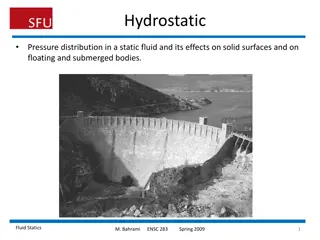
1. Introduction: The pressure center is a point on a surface immersed (such as gates) in a particular liquid. This point represents the effect of the fluid pressure force (hydrostatic force) on the surface immersed. In the case of the submerged surface horizontally, the water pressure is distributed horizontally, symmetrically, and it passing through the surface area center immersed. In the case of surface immersed vertically or inclined at a certain angle, the center of the sum of water pressure forces is under the center of the area immersed and this pressure increases as the depth increases.. 2. Objectives: 1- To find the water pressure force, which affecting a regular rectangular plate (partially or completely immersed in water). 2- To find the water pressure center (the position of the point of the water pressure force affected on the plate). 3- To find the torque moment, which resulting from the water pressure through balancing the device by placing the weight at the other end of the device and comparing the calculations with the required results.
3.Theoretical background (equations): A- Partial immersion: Figure (1): Ftheoretical = 1/2 b y2 ... (1) F= The water pressure force (hydrostatic force) delivered on a plate immersed (N) = Weight Density of water (N/m3) b = the width of plate immersed (m) y = the water height from base to free surface (m) XF = a + d - y/3 ... (2) XF = The rotating arm of hydrostatic force (m) a = The distance from top of plate immersed to beam level indication (m) d= The total height of plate (m) MF = Ftheoretical XF ... (3) MF= The moment of hydrostatic force (Nm).
Mweight= m g Xm... (4) Mweight = The moment of weight placed in balance pan (Nm) m= Mass of weight (Kg) g= the acceleration to the gravity (9.81 m/s2) Xm = The rotating arm of force delivered by weight (m) We find the actual force from through equality between MF and Mweight: Mweight= MF ... (5) m g Xm = Factual XF Factual= m g Xm / XF ... (6)
B- Complete immersion: Figure (2): Ftheoretical = (y-d/2) b d ... (7) F= The water pressure force (hydrostatic force) delivered on a plate immersed (N) = Weight Density of water (N/m3) b = the width of plate immersed (m) y = the water height from base to free surface (m) d= The total height of plate (m) XF = a + d/2 + (d2/12(y-d/2)) ... (8) XF = The rotating arm of hydrostatic force (m) a = The distance from top of plate immersed to beam level indication (m) MF = Ftheoretical XF ... (9) MF= The moment of hydrostatic force (Nm) Mweight= m g Xm ... (10) Mweight = The moment of weight placed in balance pan (Nm) m= Mass of weight (Kg)
g= the acceleration to the gravity (9.81 m/s2) Xm = The rotating arm of force delivered by weight (m) We find the actual force from through equality between MF and Mweight: Mweight= MF ... (11) m g Xm = Factual XF Factual= m g Xm / XF ... (12) Note: a= 0.2 m d= 0.1 m L= Xm = 0.276 m b= 0.075m
4. Experimental Work: 4.1. Equipment and apparatus: Figure 3, it shows the device used in the experiment, which consists of a cylinder quarter empty with its internal and external diameters (R1, and R2), respectively. The center of the cylinder quarter applies with the (x) axis, which is measured around it the required torque moment in the experiment. There is a regular plate at the bottom of the cut cylinder, the space between the cylinder surfaces forms a tank. There is no force on the side surfaces, while the torque moment produced by the forces on the plate is the only torque moment as in Figures (1, and 2). The cylinder is connected by an arm called (beam level indication), at one end, it is connecting (balance pan), which is used to balance the device when the plate is immersed in water. At the other end, another equivalent weight skier, it called (adjustable counter balance), which is used to balance the device before starting the experiment. The bottom of the cylinder is placed in a plastic tub. The basin contains Drain Cock, which used for emptying the tank. To ensure that the basin is horizontal before starting the experiment, the bubble founded in the bottom of the tub should be centered
4.2. Procedure: 1. Before starting the experiment, stabilize the device evenly by centering the bubble on the base, on which the basin is based. 2 - Stirring the adjustable counter balance until the beam level indication becomes in a horizontal position, then water pours in the basin until the water reaches the bottom edge of the cylinder quarter. 3 The suspension of the balance pan from the other side, then add water gradually until the beam level indication becomes horizontally. 4- The weights are changing gradually, then the water height in the device is recorded in each time. 5- Eight readings are recorded (4 readings in partial immersion) and (4 readings in case complete immersion), with note that the water depth in the basin is less than 100 mm in case partial immersion, while be greater than 100 mm in complete immersion.
4.3. Data Sheet: Ran The mass (g) The water depth(y) (mm) 1 2 3
5. Calculations and Results: For two case (partial immersion and complete immersion), we find: 1- The Ftheoretical by equations (1) or (7). 2- The rotating arm of hydrostatic force (m) by equations (2) or (8). 2- The moment of hydrostatic force (MF) by equations (3) or (9). 3- The moment of weight placed in balance pan (Mweight) by equations (4) or (10). 4- The actual force Facutal from through equality between MF and Mweight and using equations (6) or (12). 5- Draw diagram between the mass and the water depth (y). Ran The Ftheoretical (N). XF (m) MF (Nm) Mweight (Nm) Facutal (N) 1 2 3
6. Discussion: 1- Is there a difference between the value of theoretical and laboratory force? Why? 2- Is the force by weight the same as the experimental force? Why? 3- Any force of water pressure greater, in case of partial immersion or total immersion? Why? 4- What is the relationship between mass and the water depth? Why?
Thnke you Thank you


:")
")
:")
")