Understanding Boundary Layers in Fluid Dynamics

A boundary layer forms when a fluid flows over a solid surface, with viscous forces present close to the surface. It can be laminar or turbulent, determined by the Reynolds number. Flow separation occurs in adverse pressure gradients, affecting lift and causing drag. Efforts to delay separation include aerodynamic design features. Drag and lift forces influence an object immersed in fluid.

Download Presentation

Please find below an Image/Link to download the presentation.
The content on the website is provided AS IS for your information and personal use only. It may not be sold, licensed, or shared on other websites without obtaining consent from the author. Download presentation by click this link. If you encounter any issues during the download, it is possible that the publisher has removed the file from their server.
E N D
Presentation Transcript
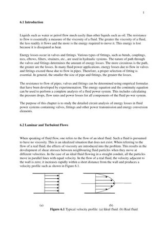
BOUNDARY LAYER MODULE 3
Whenever there is relative movement between a fluid and a solid surface, whether externally round a body, or internally in an enclosed passage, a boundary layer exists with viscous forces present in the layer of fluid close to the surface. Boundary layers can be either laminar or turbulent. A reasonable assessment of whether the boundary layer will be laminar or turbulent can be made by calculating the Reynolds number of the local flow conditions. Flow separation or boundary layer separation is the detachment of a boundary layer from a surface into a wake. Separation occurs in flow that is slowing down, with pressure increasing, after passing the thickest part of a streamline body or passing through a widening passage
Flowing against an increasing pressure is known as flowing in an adverse pressure gradient. The boundary layer separates when it has travelled far enough in an adverse pressure gradient that the speed of the boundary layer relative to the surface has stopped and reversed direction. The flow becomes detached from the surface, and instead takes the forms of eddies and vortices. The fluid exerts a constant pressure on the surface once it has separated instead of a continually increasing pressure if still attached In aerodynamics, flow separation results in reduced lift and increased pressure drag, caused by the pressure differential between the front and rear surfaces of the object.
It causes buffeting of aircraft structures and control surfaces. In internal passages separation causes stalling and vibrations in machinery blading and increased losses(lower efficiency) in inlets and compressors. Much effort and research has gone into the design of aerodynamic and hydrodynamic surface contours and added features which delay flow separation and keep the flow attached for as long as possible. Examples include the fur on a tennis ball, dimples on a golf ball, turbulators on a glider, which induce an early transition to turbulent flow; vortex generators on aircraft.
Drag The surrounding fluid exerts pressure forces and viscous forces on an object The components of the resultant force acting on the object immersed in the fluid are the drag force and the lift force. The drag force acts in the direction of the motion of the fluid relative to the object. The lift force acts normal to the flow direction. Both are influenced by the size and shape of the object and the Reynolds number of the flow.
When a high Reynolds number fluid passes around a streamlined obstacle, such as a slender plate that is aligned with the flow, a relatively thin boundary layer form on the obstacle's surface. Here, by relatively thin, we mean that the typical transverse (to the flow) thickness of the layer is ?~ (in the direction of the flow), and Re is the Reynolds number of the external flow. Suppose, however, that the obstacle is not streamlined: that is, the surface of the obstacle is not closely aligned with the streamlines of the unperturbed flow pattern. In this case, the typically observed behavior is illustrated in Figure , which shows the flow pattern of a high Reynolds number irrotational fluid around a cylindrical obstacle (whose axis is normal to the direction of the unperturbed flow). ? ??1/2, where L is the length of the obstacle
It can be seen that a stagnation point, at which the flow velocity is locally zero, forms in front of the obstacle. Moreover, a thin boundary layer covers the front side of the obstacle. The thickness of this layer is smallest at the stagnation point, and increases towards the back side of the obstacle. However, at some point on the back side, the boundary layer separates from the obstacle's surface to form a vortex-filled wake whose transverse dimensions are similar to those of the obstacle itself. This phenomenon is known as boundary layer separation.
Flow separation Flow separation occurs when: The velocity at the wall is zero or negative and an inflection point exists in the velocity profile, A positive or adverse pressure gradient occurs in the direction of flow.
Flow around a truck Flow over non-streamlined bodies such as trucks leads to considerable drag due to recirculation and separation zones. A recirculation zone is clear on the back of the cab, and another one around the edge of the trailer box. The addition of air shields to the cab roof ahead of the trailer helps organize the flow around the trailer and minimize losses, reducing drag by up to 10-15%.
TWO DIMENSIONAL WAKE AND VORTEX FORMATION A cylinder having mild variations in diameter along its span is subjected to controlled excitation at frequencies above and below the inherent shedding frequency from the corresponding two dimensional cylinder The response of the near wake is characterized in terms of timeline visualization and velocity traces, spectra, and phase plane representations It is possible to generate several types of vortex formation, depending upon the excitation frequency Globally locked in, three dimensional vortex formation can occur along the entire span of the flow Regions of locally locked in and period doubled vortex formation can exist along different portions of the span provided the excitation frequency is properly tuned
Unlike the classical subharmonic instability in free shear flows, the occurrence of period doubled vortex formation does not involve vortex coalescence instead, the flow structure alternates between two different states An experimental study of the flow around a cylinder with a single straight perturbation was conducted in a wind tunnel With this bluff body, positioned in a uniform crossflow the vortex shedding frequency and other flow characteristics could be manipulated The Strouhal number has been shown to be a function of the perturbation angular position, theta, as well as the perturbation size and Reynolds number
The perturbation size compared to the boundary layer thickness, delta, was varied from approximately 1 delta to about 20 delta The Reynolds number was varied from 10 000 to 40 000 A detailed investigation of the characteristic Strouhal number variation has shown that varying theta had a significant influence on the boundary layer separation and transition to turbulence
The Strouhal number St is a function of the Reynolds number Re (although a sufficiently varying one that it may be said that it is typically equal to 0.2, e.g. see figure below) and is proportional to the reciprocal of vortex spacing expressed as a number of obstacle diameter. It is used in the momentum transfer in general, and in both Von Karmann vortex streets and unsteady flow calculations in particular. It is normally defined in the following form : St = ?? ? where : n is the frequency of the observed phenomenon, d is the characteristic length (which is the diameter of the cylinder in the case of vortex streets), U is the velocity of the fluid.