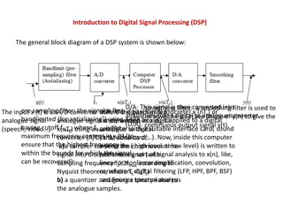
Understanding Finite Impulse Response Filtering in Digital Signal Processing
Explore the concepts of Finite Impulse Response (FIR) filtering in digital signal processing, including filter specifications for low-pass, high-pass, band-pass, and band-stop filters. Learn about frequency normalization, specifications for different filter types, and the transfer function of FIR filters.

Download Presentation

Please find below an Image/Link to download the presentation.
The content on the website is provided AS IS for your information and personal use only. It may not be sold, licensed, or shared on other websites without obtaining consent from the author. Download presentation by click this link. If you encounter any issues during the download, it is possible that the publisher has removed the file from their server.
E N D
Presentation Transcript
Finite Impulse Response Filtering EMU-E&E Engineering Erhan A. Ince Dec 2015
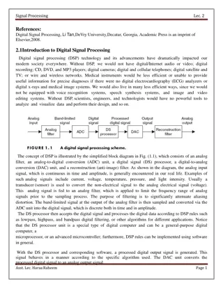
Basic concepts and FIR filter specification Figure 2-2-1 Low-pass digital filter specification Figure 2-2-1 illustrates a low-pass digital filter specification. The word specification actually refers to the frequency response specification.
p normalized cut-off frequency in the passband; s normalized cut-off frequency in the stopband; 1 maximum ripples in the passband; 2 minimum attenuation in the stopband [dB]; ap maximum ripples in the passband; and as minimum attenuation in the stopband [dB].
Frequency normalization can be expressed as follows: where: fs is a sampling frequency; f is a frequency to normalize; and is normalized frequency. Specifications for high-pass, band-pass and band-stop filters are defined almost the same way as those for low-pass filters. Figure 2-2-2 illustrates a high-pass filter specification.
Figure 2-2-3 illustrates a band-pass filter specification. Figure 2-2-3a. Band-pass digital filter specification
Transfer function of the filter is: where: bi are the feedforward filter coefficients (non-recursive part); aj are the feedback filter coefficients (recursive part); H0 is a constant; qi are the zeros of the transfer function; and pj are the poles of the transfer function.
The recursive part of the transfer function is actually a feedback of discrete-time system. FIR filters do not have this recursive part of the transfer function, so the expression above can be simplified in the following way: The impulse response of discrete-time system is obtained from inverse z-transform of the transfer function i.e. the transfer function of discrete-time system is actually the Z-transform of impulse response:
Digital FIR filters can not be derived from analog filters. Why? Rational analog filters cannot have a finite impulse response. Why try to get FIR design ? 1. They are inherently stable 2. They can be designed to have linear phase 3. There is great flexibility in shaping their magnitude response 4. It is easy to implement them.
While designing filters, it is desired to have approximately constant frequency response magnitude and zero phase in that band. For causal systems, zero-phase is not possible therefore some phase distortion must be allowed. The effect of Linear-Phase (with integer slope) is a simple time shift. A non-linear phase can have a major effect on the shape of the signal even when the frequency response magnitude is constant. Hence it is desirable to design a system with exactly or approximately linear phase.
Before a filter can be designed, a set of filter specifications must be defined. For example to design a lowpass filter with a cutoff frequency of c we start with the frequency of the ideal lowpass filter : ? ?? ??< ? ? ??? ???= ? ??? , 0 and get the unit sample response: ?? =??? ? ? ?? ? ? ? Because the filter is unrealizable (non-causal and unstable), it is necessary to relax the ideal constraint on the frequency response and allow some deviation from the ideal response. Then the specifications for a lowpass filter will be: 1 ??< ? ??? < 1 + ?? 0 ? < ?? ? ??? < ?? ?? ? ?
A general FIR filter does not have a linear phase response but this property Is satisfied when ? = ? 1 ? ? = 0,1, .., ? 1 There are four linear phase filter types : TYPE I TYPE II TYPE III TYPE IV
Linear Phase FIR Filter Design Using Windows Because hd[n] will generally be infinite in length , it is necessary to find an FIR approximation to ????? . With the window design method, the filter is designed by windowing the unit sample response: h[n] =hd[n] w[n] Where w[n] is a finite-length window that is equal to zero outside the interval 0 ? ? and is symmetric about its midpoint: w[n] = w[N-n] The effect of the window on the frequency response may be seen from the Complex convolution theorem:
Note that the ideal frequency response ????? is smoothed by the discrete-time Fourier Transform of the window (W ??? ).
The two factors that affect the design are: 1) The width of the main lobe of W ??? 2) The peak side-lobe amplitude of W ??? Ideally, the main-lobe width should be narrow, and the side-lobe amplitude should be small. However for a fixed size window, these can not be minimized independently. General Properties of windows: 1. As the length N of the window increases, the width of the main lobe decreases which results in a decrease in the width of the transition band between passband and stopband. 2. The peak side-lobe amplitude of the window is determined by the shape of the window and is independent of the window length. 3. If the window shape is changed to decrease the side-lobe amplitude, the width of the main-lobe will generally increase.