Real-Time Digital Signal Processing Lab: Matched Filtering and Digital Pulse Amplitude Modulation
Explore the concepts of transmitting one bit at a time, matched filtering, PAM systems, intersymbol interference, communication performance, and prevention of intersymbol interference in a two-level digital PAM system. The presentation covers topics like bit error probability, symbol error probability, eye diagrams, channel modeling, and techniques to mitigate interference at the receiver.
- Digital Signal Processing
- Matched Filtering
- Pulse Amplitude Modulation
- Interference Mitigation
- Communication Systems

Download Presentation

Please find below an Image/Link to download the presentation.
The content on the website is provided AS IS for your information and personal use only. It may not be sold, licensed, or shared on other websites without obtaining consent from the author. Download presentation by click this link. If you encounter any issues during the download, it is possible that the publisher has removed the file from their server.
E N D
Presentation Transcript
ECE 445S Real-Time Digital Signal Processing Lab Fall 2024 Matched Filtering and Digital Pulse Amplitude Modulation (PAM) Slides by Prof. Brian L. Evans and Dr. Serene Banerjee Dept. of Electrical and Computer Engineering The University of Texas at Austin Lecture 14 http://www.ece.utexas.edu/~bevans/courses/realtime
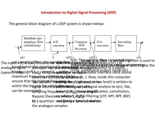
Outline ( ) 1t x A Transmitting one bit at a time b t 1 bit Matched filtering (t ) y PAM system h+ b Intersymbol interference t b Communication performance Bit error probability for binary signals Symbol error probability 0 bit 1 bit Eye diagram (in lab)
Transmitting One Bit Transmission on communication channels is analog Two-level digital pulse amplitude modulation (PAM) receive 0 bit ( ) x 0t 0 bit ( ) y 0t input output b b Additive Noise Channel t t x(t) y(t) -A -A receive 1 bit ( ) ( ) 1t y 1t x How does the receiver decide which bit was sent? A A b b t t 1 bit 14 - 3
Transmitting One Bit Two-level digital pulse amplitude modulation over channel that has memory but does not add noise ( ) y 0t ( ) x 0t input output b h+ b h Communication Channel t t x(t) y(t) -A Th -A Model channel as LTI system ( ) 1t x ( ) 1t y A A Th t t Approximate infinite impulse response as a rectangular pulse for timing analysis c(t) b t h h+ b 1 Bit of 0 or 1 Assume Th < Tb h t
Transmitting Two Bits (Interference) Transmitting two bits (pulses) back-to-back will cause overlap (interference) at the receiver (t ) c (t ) x (t ) y * = 1 A h+ b b h t b b t t -A Th Assume that Th < Tb 0 bit 1 bit 0 bit 1 bit Sample y(t) at Tb, 2 Tb, , and threshold with threshold of zero How do we prevent intersymbol interference (ISI) at the receiver? Intersymbol interference 14 - 5
Preventing ISI at Receiver Option #1: wait Th seconds between pulses in transmitter (called guard period or guard interval) ) (t c ) (t x (t ) y * = 1 A h+ b h+ b h t b h b t t -A Th Assume that Th < Tb 0 bit 1 bit 0 bit 1 bit Option #2: use channel equalizer in receiver FIR filter designed via training sequences sent by transmitter Design goal: cascade of channel memory and channel equalizer should give all-pass frequency response 14 - 6
Digital 2-level PAM System Receiver Transmitter an y(ti) x(t) y(t) 1 0 1 J s*(t) Serial/ Parallel Decision Block h(t) Map Interpolation Sample at t = i Tsym matched filter symbol amplitude bits baseband waveform symbol of bits bits Transmitted signal Interpolation pulse shape g(t) with g(0) = 1 and g(k Tsym) = 0 for ? 0 and with lowpass frequency content Reliable communication requires synchronization of symbol clocks between transmitter and receiver 14 - 7
Matched Filter Detection of pulse in presence of additive noise Receiver knows what pulse shape it is looking for Channel memory ignored (assumed compensated by other means, e.g. channel equalizer in receiver) g(t) y(T) x(t) y(t) T is the symbol period h(t) t = T Pulse shape Matched filter w(t) = + ( ) ( ) t * ( n ) t ( ) * ( ) y t g t h + t w t h t Additive white Gaussian noise (AWGN) with zero mean and variance N0 /2 = ( ) ( ) g 0 14 - 8
Matched Filter Derivation Design of matched filter Maximize signal power i.e. power of at t = T Minimize noise i.e. power of Combine design criteria Maximize ?, where ? is peak pulse SNR ? =|?0T |2 average noise power = ( ) ( ) * ( ) g t g t h t 0 = ( ) ( ) * ( ) n t w t h t T is the symbol period ?{?2(t)}= instantaneous signal power g(t) y(T) x(t) y(t) h(t) t = T Pulse signal Matched filter w(t) 14 - 9
Power Spectra Deterministic signal x(t) w/Fourier transformX(f) Power spectrum is square of absolute value of magnitude response (phase is ignored) ( ) ( X f Px = Multiplication in Fourier domain is convolution in time domain Conjugation in Fourier domain is reversal & conjugation in time Autocorrelation of x(t) = * ( ) ( ) * ( ) Rx x x Maximum value (when it exists) is at Rx(0) Rx( ) is even symmetric, i.e. Rx( ) = Rx(- ) 2 = * ) ( ) ( ) f X f X f x(t) 1 0 Ts t Rx( ) Ts ) = * * ( ) ( ) ( ) * ( X f X f F x x -Ts Ts
Power Spectra ) Two-sided random signal n(t) Fourier transform may not exist, but power spectrum exists ( ) ( ) ( ) ( = = when 0 ) ( ) ( ) ( = + = t n t n E Rn = ( ) ( P f F R n n = + = + * * ( ) n ( ) ( ) ( ) ( ) Rn E t n t n t n t dt time-averaged = * * * ) ( ) ( ) * ( ) Rn E n t n t n t n t dt n n For zero-mean Gaussian random processn(t)with variance 2 * 0 = 2 ( ) Pn f = + = * 2 ( ) ( ) ( ) ( ) Rn Estimate noise power spectrum in Matlab E n t n t approximate noise floor N = 16384; % finite no. of samples gaussianNoise = randn(N,1); plot( abs(fft(gaussianNoise)) .^ 2 ); 14 - 11
Matched Filter Derivation Noise power spectrum SW(f) g(t) y(T) x(t) y(t) h(t) N 0 t = T Pulse signal 2 Matched filter w(t) f =N0 |H( f )|2 SN(f )=SW(f ) SH(f ) = Noise ( ) ( ) * ( ) n t w t h t 2 Matched filter AWGN N 2 g ) t = = 2 2 { ( } ) ( ) | ( | ) 0 E n t S f df H f df N = = Signal ( ) ( ) ( ) ( ) ( ) * ( G f H f G f t g t h 0 0 = j 2 f t ( ) ( ) ( ) df g t H f G f e T is the symbol period 0 2 j | = 2 2 f T | ( | ) T ( ) ( ) | g H f G f e df 14 - 12 0
Matched Filter Derivation Find h(t) that maximizes pulse peak SNR j 2 T 2 f a | ( ) ( ) df | H f G f e = N 2 2 | ( | ) H f df 0 b Schwartz s inequality For vectors: T a b || = * T a b a b | | || || || cos a b || || || || 2 - - - 2 2 * 2 For functions: ( ) ( ) ( ) ( ) x x dx x dx x dx 1 1 2 = ( ) ( ) x k x k R upper bound reached iff 1 2 14 - 13
Matched Filter Derivation = = * 2 j f T Let ( ) ( ) and ( ) ( ) f H f f G f e 1 2 2 j 2 2 2 f T ( ) ( ) | | ( | ) | ( | ) | H f G f e df H f df G f df - 2 j 2 f T ( ) ( ) | | H f G f e df 2 = 2 | ( | ) G f df - N N 2 0 | ( | ) H f df 0 T is the symbol period 2 2 = 2 | ( | ) which , df occurs when G f max N 0 = * 2 j f T ( ) ( = ) Schwartz by inequality s ' H f k G f e k opt * Hence, ( ) ( ) h t k g T t opt 14 - 14
Matched Filter Impulse response is hopt(t) = kg*(T - t) Symbol period T, transmitter pulse shape g(t)and gain k Scaled, conjugated, time-reversed, and shifted version of g(t) Duration and shape determined by pulse shape g(t) Maximizes peak pulse SNR 2 N 2 2 E = = = = 2 2 | ( | ) | ( | ) t SNR b G f df g dt max N N 0 0 0 Does not depend on pulse shape g(t) Proportional to signal energy (energy per bit) Eb Inversely proportional to power spectral density of noise 14 - 15
Matched Filter for Rectangular Pulse Matched filter for causal rectangular pulse shape Impulse response is causal rectangular pulse of same duration Convolve input with rectangular pulse of duration T sec and sample result at T sec is same as First, integrate for T sec Second, sample at symbol period T sec Third, reset integration for next time period Integrate and dump circuit Sample and dump T t=nT h(t) = ___ 14 - 16
Bit Error Probability for 2-PAM Tbis bit period (bit rate is fb = 1/Tb) s(t) r(t) k r(t) rn = ( ) ( T ) s t a g t k k b h(t) r(t)=s(t)+w(t) r(t) = h(t) * r(t) Sample at t = nTb Matched filter w(t) w(t) is spectrally flat noise that follows a Gaussian distribution with zero mean and variance 2 Lowpass filtering a Gaussian random process produces another Gaussian random process Mean scaled by H(0) Variance scaled by twice lowpass filter s bandwidth Matched filter s bandwidth is fb 14 - 18
Bit Error Probability for 2-PAM Noise power at matched filter output Filtered noise T = Tsym ) = ( d ) ( ) ) ( v nT h w nT 2 Noise power = 2 ( ( ) ( ) E v nT E h w nT d g = d d { ( ) ( ) ( ) ( ) } E g w nT g w nT 1 1 2 2 1 2 T T = d d ( ) ( ) { ( ) ( )} g E w nT w nT 1 2 1 2 1 2 T T 2 ( 1 2) / 2 2 1 sym = = = 2 2 2 2 ( ) ( ) h d H d 2 T / 2 14 - 19 sym
Bit Error Probability for 2-PAM Symbol amplitudes of +A and -A Rectangular pulse shape with amplitude 1 Bit duration (Tb) of 1 second Matched filtering with gain of one (see slide 14-15) Integrate received signal over nth bit periodand sample + (n ) r r P n 1 n n = ( ) r r t dt n + 1 n nr = + ( ) A w t dt - 0 A A n v Probability density function (PDF) = + A n 14 - 20
Bit Error Probability for 2-PAM Probability of error given that transmitted pulse has amplitude A Tb = 1 v A = = + = = error ( | ( ) ) ( ) 0 ( ) n P s nT A P A v P v A P b n n Random variable / PDF for nv nv PDF for N(0, 1) is Gaussian with zero mean and variance of one / A 0 2 A v 1 v A A = = = = ( error | ( ) ) e dv n P s nT A P Q 2 2 Q function is on next slide 14 - 21
Q Function Q function 1 2 = / 2 y ( ) Q x e dy x 2 Complementary error function erfc 2 2 = tdt ( ) erfc x e x Erfc[x] in Mathematica Relationship 1 x = erfc(x) in Matlab ( ) Q x erfc 2 2 14 - 22
Bit Error Probability for 2-PAM Probability of error given that transmitted pulse has amplitude A ) ( | error ( A nT s P b = Assume that 0 and 1 are equally likely bits Tb = 1 = ) ( / ) Q A = = + = ( error) ( ) ( error | ( ) ) A ( ) ( error | ( ) ) P P A P s nT A P A P s nT A b b ( ) 1 1 A A = + = = Q Q Q Q 2 2 2 A 2 = = where, Probability of error exponentially decreases with SNR (see slide 8-16) SNR 1 e 2 ( ) Q 2 for large positive 14 - 23
PAM Symbol Error Probability Set symbol time (Tsym) to 1 second Average transmitted signal power 3 d d d 1 = = 2 n 2 2 n { } | ( | ) { } Signal P E a G d E a T 2 d -d GT( ) square root raised cosine spectrum 3 d M-level PAM symbol amplitudes 2-PAM 4-PAM M M = = , , 0 , , 1 . . . + . . . 2 ( d ), 1 li i i Constellation points with receiver decision boundaries 2 2 With each symbol equally likely M M 2 1 M 2 M d 2 2 ( ) = 2 = = ) 1 = ) 1 2 i 2 2 ( d ( P l i M Signal 3 M 1 i = + 1 i 2 14 - 24
PAM Symbol Error Probability Noise power and SNR Consider M-2 inner levels in constellation Error only if where Probability of error is / 2 1 N N sym = = 0 0 P d vn | 2 / 0 | d Noise 2 2 2 / 2 sym = 2 N two-sided power spectral density of AWGN d P ) 1 2 2 ( 2 M d | = (| ) 2 P v d Q Signal = = SNR n 3 P N 0 Noise Consider two outer levels in constellation Assume ideal channel, i.e. one without ISI d = ( ) P v d Q = + r a v n n n n channel noise after matched filtering and sampling 14 - 25
PAM Symbol Error Probability Assuming that each symbol is equally likely, symbol error probability for M-level PAM 2 2 ( 2 ) 1 M d d M d = + = 2 Pe Q Q Q M M M M-2 interior points 2 exterior points Symbol error probability in terms of SNR 1 P 2 ( ) 1 1 3 2 M d 2 Signal = = = 2 2 SNR since SNR P Q M e 2 1 3 M M P Noise 14 - 26
Eye Diagram for 2-PAM Useful for PAM transmitter and receiver analysis and troubleshooting Sampling instant M=2 Margin over noise Distortion over zero crossing Slope indicates sensitivity to timing error Interval over which it can be sampled t - Tsym t t + Tsym The more open the eye, the better the reception 14 - 27
Eye Diagram for 4-PAM Due to startup transients. 3d Fix is to discard first few symbols equal to number of symbol periods in pulse shape. d -d -3d 14 - 28
Optional Symbol Clock Recovery Transmitter and receiver normally have different oscillator circuits Critical for receiver to sample at correct time instances to have max signal power and min ISI Receiver should try to synchronize with transmitter clock (symbol frequency and phase) First extract clock information from received signal Then either adjust analog-to-digital converter or interpolate Next slides develop adjustment to A/D converter Also, see Handout M in the reader 14 - 29
Optional Symbol Clock Recovery g1(t) is impulse response of LTI composite channel of pulse shaper, noise-free channel, receive filter = = = k m = = = = * s*(t) is transmitted signal ( ) ( ) ( ) ( ) q t s t g t a g t kT 1 1 k sym k g1(t) is deterministic = = 2 ( ) ( ) a a ( ) ( ) p t q t g t kT g t mT 1 1 k m sym sym = { ( )} { } ( ) ( ) E p t E a a g t kT g t mT E{akam} = a2 [k-m] 1 1 k m sym sym k m = = 2 2 1 Periodic with period Tsym ( ) a g t kT sym k p(t) Receive B( ) BPF H( ) x(t) Squarer PLL 14 - 30 q(t) q2(t) z(t)
Optional Symbol Clock Recovery Fourier series representation of E{ p(t) } e p t p E )} ( { = 1 sym T j k t = j k t = { ( )} p E p t e dt sym sym where k k T 0 k sym In terms of g1(t) and using Parseval s relation ( ) T sym 2 2 ( ) ( G ) a a jk t = = k d 2 1 p g t e dt G sym 1 1 k sym 2 T sym Fourier series representation of E{ z(t) } ( = = k H k H p z sym k k 2 ) ( ) ( ) ( G ) a k d G 1 1 sym sym 2 T sym p(t) Receive B( ) BPF H( ) x(t) Squarer PLL 14 - 31 q(t) q2(t) z(t)
Optional Symbol Clock Recovery With G1( ) = X( ) B( ) Choose B( ) to pass sym pk = 0 except k =-1, 0, 1 ( = = k H k H p Z sym sym k k 2 ) ( ) ( ) ( G ) a k d G 1 1 sym 2 T sym Choose H( ) to pass sym Zk= 0except k = -1, 1 ( ) e e Z t z E k jk t j t j t = = + = 2 cos( ) e t sym sym sym k sym B( ) is lowpass filter with passband = sym H( ) is bandpass filter with center frequency sym p(t) Receive B( ) BPF H( ) x(t) Squarer PLL 14 - 32 q(t) q2(t) z(t)


")