Understanding Power System Stability: Synchronous Machines and Dynamics
Power system stability is crucial for maintaining synchronism and continuity. It includes steady-state and transient stability, with dynamics of synchronous machines playing a key role. Different types of disturbances can affect stability, requiring a system's ability to adjust and return to normal conditions. The concepts of inertia constant and kinetic energy dynamics are fundamental in analyzing power system stability.
Download Presentation

Please find below an Image/Link to download the presentation.
The content on the website is provided AS IS for your information and personal use only. It may not be sold, licensed, or shared on other websites without obtaining consent from the author. Download presentation by click this link. If you encounter any issues during the download, it is possible that the publisher has removed the file from their server.
E N D
Presentation Transcript
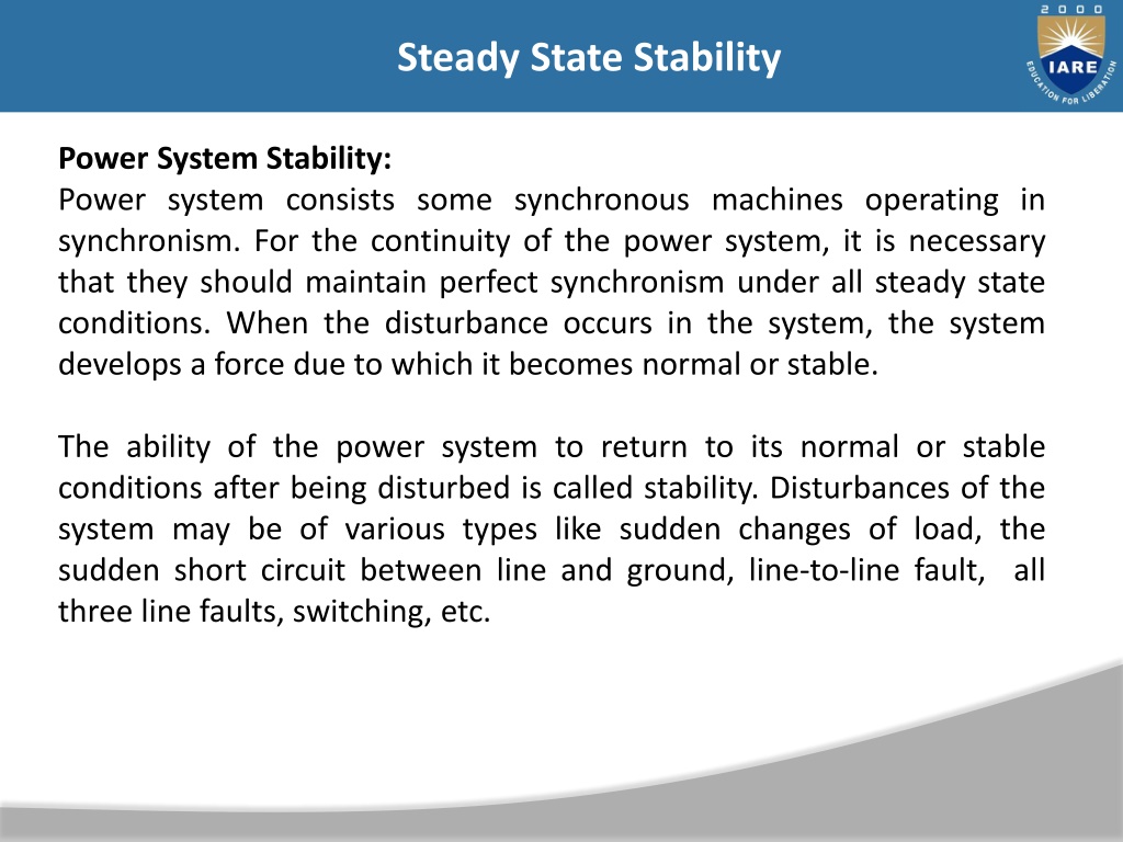
Steady State Stability INTRODUCTION INTRODUCTION Power System Stability: Power system consists some synchronous machines operating in synchronism. For the continuity of the power system, it is necessary that they should maintain perfect synchronism under all steady state conditions. When the disturbance occurs in the system, the system develops a force due to which it becomes normal or stable. The ability of the power system to return to its normal or stable conditions after being disturbed is called stability. Disturbances of the system may be of various types like sudden changes of load, the sudden short circuit between line and ground, line-to-line fault, all three line faults, switching, etc.
Steady State Stability The stability of the system mainly depends on the behaviour of the synchronous machines after a disturbance. The stability of the power system is mainly divided into two types depending upon the magnitude of disturbances Steady state stability Transient stability
Steady State Stability Steady-state stability It refers to the ability of the system to regain its synchronism (speed & frequency of all the network are same) after slow and small disturbance which occurs due to gradual power changes. Steady-state stability is subdivided into two types Dynamic stability It denotes the stability of a system to reach its stable condition after a very small disturbance (disturbance occurs only for 10 to 30 seconds). It is also known as small signal stability. It occurs mainly due to the fluctuation in load or generation level. Static stability It refers to the stability of the system that obtains without the aid (benefit) of automatic control devices such as governors and voltage regulators. Transient Stability It is defined as the ability of the power system to return to its normal conditions after a large disturbance. The large disturbance occurs in the system due to the sudden removal of the load, line switching operations; fault occurs in the system, sudden outage of a line, etc.
Steady State Stability Dynamics of a Synchronous Machine: Dynamics of a Synchronous Machine kinetic energy of the rotor at synchronous machine is Where ws = (P/2) wsm, But,
Steady State Stability Where, We shall define the inertia constant H such that, Where,
Steady State Stability It immediately follows that, M is also called the inertia constant. Taking G as base, the inertia constant in pu is M(P.U) = H/(Pi.f) = H/(180.f) i
Steady State Stability Swing Equation: It is assumed that the windage, friction and iron-loss torque is negligible. The differential equation governing the rotor dynamics can then be written as The transient stabiity of the system can be determined by the help of the swing equation. Let be the angular position of the rotor at any instant t. is continuously changing with time, and it is convenient to measure it with respect to the reference axis shown in the figure below. The angular position of the rotor is given by the equation
Steady State Stability Constructing Constructing Y Ybus bus for power for power- -flow analysis flow analysis
Steady State Stability Load angle (or Torque angle) : For a synchronous generator, the magnetic field rotates at synchronous speed and the rotating magnetic field is created in the stator. These two fields are not fully aligned. The stator field lags the rotating field. This lagging expressed in angle is called load angle. Power angle : For a generator, the power angle is the difference between the generator induced voltage and the generator terminal voltage. The value of the power angle is same as the load angle. So, in context of generator, power angle and load angle mean same thing. For the case of transmission line the power angle is the angle between the angles of the voltages at two different points (bus). The transfer of power between the two points of power system is proportional to the sine of this angle.
Steady State Stability Where, angle between rotor field and a reference axis ws synchronous speed angular displacement Differentiation of equation (1) give Differentiation of equation (2) gives
Steady State Stability Angular acceleration of rotor Power flow in the synchronous generator is shown in the diagram below. If the damping is neglected the accelerating torques, Tain a synchronous generator is equal to the difference of mechanical input shaft and the electromagnetic output torque, i.e.,
Steady State Stability Where, Ta accelerating torque Ts shaft torque Te electromagnetic torque Angular momentum of the rotor is expressed by the equation M = Jw ---------------------- 6 Where, w- the synchronous speed of the rotor J moment of inertia of the rotor M angular momentum of the rotor Multiplying both the sides of equation (5) by w we get
Steady State Stability Where, Ps mechanical power input Pe electrical power output Pa accelerating power But, Equation (7) gives the relation between the accelerating power and angular acceleration. It is called the swing equation. Swing equation describes the rotor dynamics of the synchronous machines and it helps in stabilizing the system.
Steady State Stability Steady State Stability: As an introduction, we need to know about power state stability. It is really the capability of the system to return to its steady state condition after subjected to certain disturbances. We can now consider a synchronous generator to understand the power system stability. The generator is in synchronism with the other system connected to it. The bus connected to it and the generator will have same phase sequence, voltage and the frequency. So, we can say that the power system stability here is the capability of the power system to come back to its steady condition without affecting synchronism when subjected to any disturbances. This system stability is classified into Transient Stability, Dynamic Stability and Steady State Stability.
Steady State Stability It is the study which implies small and gradual variations or changes in the working state of the system. The purpose is to determine the higher limit of loading in the machine before going to lose the synchronism. The load is increased slowly. The highest power which can be transferred to the receiving end of the system without affecting the synchronism is termed as Steady State Stability limit.
Steady State Stability The Swings equation is known by Pm Mechanical power Pe Electrical power Load angle H Inertia constant s Synchronous speed
Steady State Stability Consider the above system (figure above) which is operating on steady state power transfer of Assume the power is increased by a small amount say Pe. As a result, the rotor angle becomes from 0.
Steady State Stability p frequency of oscillation. The characteristic equation is used to determine the system stability due to small changes. Conditions for System Stability
Steady State Stability Without loss of stability, the Maximum power transfer is given by Assume, the condition when the system is in operation with lower than the steady state stability limit. Then, it may oscillate continuously for a lengthy time if the damping is very low.
Steady State Stability The oscillation which persists is a hazard to system security. The |Vt| should be kept constant for each load by adjusting the excitation. This is to maintain the steady state stability limit. A system can never be operated higher than its steady state stability limit but it can operate beyond the transient stability limit. By reducing the X (reactance) or by raising the |E| or by increasing the |V|, the improvement of steady state stability limit of the system is possible. Two systems to improve the stability limit are quick excitation voltage and higher excitation voltage. To reduce the X in the transmission line which is having high reactance, we can employ parallel line.
Steady State Stability Transfer reactance: Transfer reactance is the reactance between sending end node and receiving end node under fault conditions. X transfer reactance E- sending end voltage V- receiving end voltage
Steady State Stability Multi Machine System:- In a multi machine system a common base must be selected. Let Gmachine = machine rating (base) Gsystem = system base From swing equation we can write
Steady State Stability Machines Swinging in Unison (Coherently) :- Let us consider the swing equations of two machines on a common system base, i.e., Since the machines rotor swing in unison,
Steady State Stability Simplifying above all equations Equivalent inertia Heq can be expressed as:
Steady State Stability A 60 Hz, 4 pole turbo-generator rated 100MVA, 13.8 KV has inertia constant of 10 MJ/MVA. (a) Find stored energy in the rotor at synchronous speed. (b) If the input to the generator is suddenly raised to 60 MW for an electrical load of 50 MW, find rotor acceleration. (c) If the rotor acceleration calculated in part (b) is maintained for 12 cycles, find the change in torque angle and rotor speed in rpm at the end of this period. (d) Another generator 150 MVA, having inertia constant 4 MJ/MVA is put in parallel with above generator. Find the inertia constant for the equivalent generator on a base 50 MVA.
Steady State Stability Example2:- Find the maximum steady-state power capability of a system consisting of a generator equivalent reactance of 0.4pu connected to an infinite bus through a series reactance of 1.0 p.u. The terminal voltage of the generator is held at1.10 p.u. and the voltage of the infinite bus is 1.0 p.u.
Steady State Stability Synchronizing Power and Torque Coefficient Definition: Synchronizing Power is defined as the varying of the synchronous power P on varying in the load angle . It is also called Stiffness of Coupling, Stability or Rigidity factor. It is represented as Psyn. A synchronous machine, whether a generator or a motor, when synchronised to infinite Busbars has an inherent tendency to remain in Synchronism. Consider asynchronous generator transferring a steady power Paat a steady load angle 0. Suppose that, due to a transient disturbance, the rotor of the generator accelerates, resulting from an increase in the load angle by d . The operating point of the machine shifts to a new constant power line and the load on the machine increases to Pa+ P.
Steady State Stability The steady power input of the machine does not change, and the additional load which is added decreases the speed of the machine and brings it back to synchronism. Similarly, if due to a transient disturbance, the rotor of the machine retards resulting a decrease in the load angle. The operating point of the machine shifts to a new constant power line and the load on the machine decreases to (Pa P). Since the input remains unchanged, the reduction in load accelerates the rotor. The machine again comes in synchronism. The effectiveness of this correcting action depends on the change in power transfer for a given change in load angle. The measure of effectiveness is given by Synchronising Power Coefficient.
Steady State Stability Power output per phase of the cylindrical rotor generator The synchronising torque coefficient
Steady State Stability In many synchronous machines Xs>> R. Therefore, for a cylindrical rotor machine, neglecting saturation and stator resistance equation (3) and (5) becomes For a salient pole machine
Steady State Stability Unit of Synchronizing Power Coefficient Psyn The synchronising Power Coefficient is expressed in watts per electrical radian. Therefore, Since, radians = 180 1 radian = 180/ degrees
Steady State Stability If P is the total number of pair of poles of the machine. Synchronising Power Coefficient per mechanical radian is given by the equation shown below.
Steady State Stability Synchronising Power Coefficient per mechanical degree is given as Synchronising Torque Coefficient: Synchronising Torque Coefficient gives rise to the synchronising torque coefficient at synchronous speed. That is, the Synchronizing Torque is the torque which at synchronous speed gives the synchronising power. If synis the synchronising torque coefficient than the equation is given as shown below.
Steady State Stability m is the number of phases of the machine s= 2 ns nsis the synchronous speed in revolution per second
Steady State Stability Significance of Synchronous Power Coefficient: The Synchronous Power Coefficient Psynis the measure of the stiffness between the rotor and the stator coupling. A large value of Psynindicates that the coupling is stiff or rigid. Too rigid a coupling means and the machine will be subjected to shock, with the change of load or supply. These shocks may damage the rotor or the windings. We have,
Steady State Stability The above two equations (17) and (18) show that Psynis inversely proportional to the synchronous reactance. A machine with large air gaps have relatively small reactance. The synchronous machine with the larger air gap is stiffer than a machine with a smaller air gap. Since Psynis directly proportional to Ef, an overexcited machine is stiffer than an under the excited machine. The restoring action is great when = 0, that is at no load. When the value of = 90 , the restoring action is zero. At this condition, the machine is in unstable equilibrium and at steady state limit of stability. Therefore, it is impossible to run a machine at the steady state limit od stability since its ability to resist small changes is zero unless the machine provided with special fast acting excitation system.
Steady State Stability Methods of improving stability when the maximum power limit of various power-angle curves is raised, the accelerating area decreases and decelerating area increases for a given clearing angle. Consequently, 0 is decreased and m 1s increased. This means that by increasing Pmaxthe rotor can swing through a larger Pmaxincreases the critical clearing time and improves stability. The steady-state power limit is given by Pmax=EV/X It can be seen from this expression that P max can be increased by increasing either or both V and E and reducing the transfer reactance. The following methods are available for reducing the transfer reactance:
Steady State Stability 1. Operate Transmission Lines in Parallel By operating transmission lines in parallel reactance decreases and power increases. 2. Use of Double-Circuit Lines The impedance of a double-circuit line is less than that of a single-circuit line. A double-circuit line doubles the transmission capability. An additional advantage is that the continuity of supply is maintained over one line with reduced capacity when the other line is out of service for maintenance or repair. But the provision of additional line can hardly be justified by stability consideration alone.
Steady State Stability 3. Use of Bundled Conductors Bundling of conductors reduces to a considerable extent the line reactance and so increases the power limit of the line. 4. Series Compensation of the Lines The inductive reactance of a line can be reduced by connecting static capacitors in with the line.It is to be noted that any measure to increase the steady-state limit Pmax will improve the transient stability limit. The use of generators of high inertia and low reactance improves the transient stability, but generators with these characteristics are costly. In practice, only those methods are used which are economical.
Steady State Stability 5. High-Speed Excitation Systems High-Speed excitation helps to maintain synchronism during a fault by quickly increasing the excitation voltage. High-speed governors help by quickly adjusting the generator inputs. 6. Fast Switching Rapid isolation of faults is the principal way of improving transient stability. The fault should be cleared as fast as possible. It so the time required for fault removal is the sum of relay response time plus the circuit breaker operating time. Therefore, high speed relaying and circuit breaking are commonly used to improve stability during fault conditions. It has now become possible to isolate the fault in less than two cycles (that is. 0.04 s for 50 Hz system). System stability can be further improved by making circuit-breaker reclosure automatic,
Steady State Stability as many faults do not re-establish themselves after restoration of supply. The time interval between removal and reclosure should be reduced keeping in mind that the line must remain de- energized for a certain minimum time in order that the line insulation should recover fully. 7.Breaking Resistors In this method an artificial electric load in the form of shunt resistors is temporarily connected at or near the generator bus. Such resistors partially compensate the reduction of load on a generator following a fault. The acceleration of the generator rotor is therefore, reduced. For this reason, these resistors are called braking resistors. This method is also known as dynamic braking. A control scheme connects the through circuit breakers.
Steady State Stability The scheme also amounts of resistance to be connected and the duration of its connection. the immediately following the fault and remain in the circuit for few cycles. They are disconnected at the moment of enclosure when the system voltage has recovered. braking resistors are connected 8. Single-Pole Switching Majority of the line faults are single line-to-ground (LG) faults. In single-pole switching (also called independent pole operation), the three phases of the circuit breaker are closed or opened independently of each other. In the event of an LG fault, the circuit breaker pole corresponding to the faulty line is opened and the remaining two healthy phases continue to transfer power. Since most of the faults are transitory, this phase can be reclosed after it has been open for a predetermined time.
Steady State Stability The System should not be operated for long periods with one phase open. Therefore, provision should be made to trip the whole line if one phase remains open predetermined time . 9. HVDC Links High voltage direct current (HVDC) links are helpful in maintain in stability the following advantages A dc. tie line provides a loose coupling between two ac. Systems to be interconnected. A d.c link may be interconnect two a.c systems at different frequencies. There is no transfer of fault energy from one a.c. system to another if they are interconnected by a d. . tie line.
Steady State Stability 10. Load Shedding If there is insufficient generation to maintain system frequency, some of the generators are disconnected immediately or during after a fault. the stability of the remaining generators is improved. The unit to be disconnected is provided with a large steam bypass system. When the system recovers from the shock of the fault, the disconnected unit is resynchronized and reloaded. Extra cost of a large steam bypass system is the limitation of this method.
