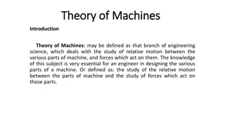
Introduction to Kinematics and Dynamics of Machines (KDM) with Mechanisms and Machines
This chapter introduces the fundamentals of mechanisms and machines in the context of Kinematics and Dynamics of Machines (KDM) at L.E. College, Morbi-2. It covers topics such as Degrees of Freedom, Kutzbach Criterion, Grubler's Criterion, Inversion of Mechanism, Types of Kinematic Chains, and Grashoff's Law.

Download Presentation

Please find below an Image/Link to download the presentation.
The content on the website is provided AS IS for your information and personal use only. It may not be sold, licensed, or shared on other websites without obtaining consent from the author. Download presentation by click this link. If you encounter any issues during the download, it is possible that the publisher has removed the file from their server.
E N D
Presentation Transcript
KINEMATICS & DYNAMICS OF MACHINES (KDM) L. E. College, Morbi-2 Industrial Engineering Department Chapter-01 Introduction of Mechanisms and Machines Prepared by Prof. Divyesh B. Patel Mechanical Engg. Dept LE. College, Morbi +919925282644 divyesh21dragon@gmail.com
Number of Degrees of Freedom (movability ) for Plane Mechanisms For Space
Number of Degrees of Freedom (movability ) for Plane Mechanisms
Kutzbach Criteron to Plane Mechanisms n = 3 (l 1) 2 j h n = Numeber of degree of freedom l = Number of Links j = Number of Joints of lower pair h = Number of higher pair Where
Grublers Criterion for Plane Mechanisms The Grubler s criterion applies to mechanisms with only single degree of freedom joints where the overall movability of the mechanism is unity. 1 = 3 (l 1) 2 j or 3l 2j 4 = 0
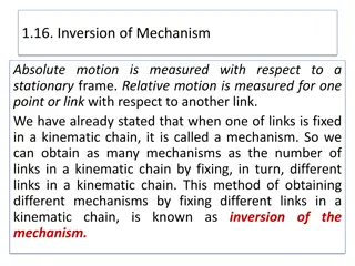
Inversion of Mechanism When one of links is fixed in a kinematic chain, it is called a mechanism. So we can obtain as many mechanisms as the number of links in a kinematic chain by fixing, in turn, different links in a kinematic chain. This method of obtaining different mechanisms by fixing different links in a kinematic chain, is known as inversion of the mechanism.
Types of Kinematic Chains 1. Four bar chain or quadric cyclic chain, 2. Single slider crank chain, and 3. Double slider crank chain.
Grashoffs Law It states that for planer 4-bar linkage, sum of the shortest and longest link lengths must be less than or equal to sum of the remaining link lengths, If there is to be continuous relative motion between 2 members S+L P+Q
Inversion of Four-Bar chain 1) First inversion: coupled wheel of locomotive The mechanism of a coupling rod of a locomotive (also known as double crank mechanism) which consists of four links is shown in Fig. coupled wheel of locomotive In this mechanism, the links AB and DC (having equal length) act as cranks and are connected to the respective wheels. The link BC acts as a coupling rod and the link AD is fixed in order to maintain a constant centre to Centre distance between them. This mechanism is meant for transmitting rotary motion from one wheel to the other wheel
2) Second inversion: Beam Engine A part of the mechanism of a beam engine (also known as cranks and lever mechanism) which consists of four links is shown in Fig. In this mechanism, when the crank rotates about the fixed centre A, the lever oscillates about a fixed centre D. The end E of the lever CDE is connected to a piston rod which reciprocates due to the rotation of the crank. beam engine In other words, the purpose of this mechanism is to convert rotary motion into reciprocating motion.
3) Third inversion: watts indicator mechanism A Watt s indicator mechanism (also known as Watt's straight line mechanism or double lever mechanism) which consists of four links is shown in Fig. The four links are: fixed link at A, link AC, link CE and link BFD. It may be noted that BF and FD form one link because these two parts have no relative motion between them. The links CE and BFD act as levers. The displacement of the link BFD is directly proportional to the pressure of gas or steam which acts on the indicator plunger. On any small displacement of the mechanism, the tracing point E at the end of the link CE traces out approximately a straight line. watts indicator mechanism

 for")
 for")
 for")


")
")