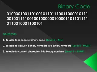
Understanding MIPS Instruction Sets and Binary Execution

This lecture covers the mapping of MIPS instructions to binary for execution, the use of pseudo-instructions to improve code readability, and the handling of large constants. It discusses levels of representation and interpretation, the concept of stored-program computers, addressing in memory, binary compatibility of programs, and the evolution of instruction sets over time.

Download Presentation

Please find below an Image/Link to download the presentation.
The content on the website is provided AS IS for your information and personal use only. It may not be sold, licensed, or shared on other websites without obtaining consent from the author. Download presentation by click this link. If you encounter any issues during the download, it is possible that the publisher has removed the file from their server.
E N D
Presentation Transcript
3. INSTRUCTION SETS III Rocky K. C. Chang Version 0.1, 14 September 2017
GOALS OF THIS LECTURE Understand how MIPS instructions are mapped to binary for execution. Understand how pseudo-instructions can help make the assembly code easier to read. Understand how large constants are handled. 2
LEVELS OF REPRESENTATION/INTERPRETATION temp = v[k]; v[k] = v[k+1]; v[k+1] = temp; High Level Language Program (e.g., C) Compiler lw $t0, 0($2) lw $t1, 4($2) sw $t1, 0($2) sw $t0, 4($2) Anything can be represented Assembly Language Program (e.g., MIPS) as a number, i.e., data or instructions Assembler 0000 1001 1100 0110 1010 1111 0101 1000 1010 1111 0101 1000 0000 1001 1100 0110 1100 0110 1010 1111 0101 1000 0000 1001 0101 1000 0000 1001 1100 0110 1010 1111 Machine Language Program (MIPS) Machine Interpretation Hardware Architecture Description (e.g., block diagrams) Architecture Implementation Logic Circuit Description (Circuit Schematic Diagrams) 3
BIG IDEA: STORED-PROGRAM COMPUTER Instructions are represented as bit patterns - can think of these as numbers. Therefore, entire programs can be stored in memory to be read or written just like data. Can reprogram quickly (seconds), don t have to rewire computer (days) Known as the von Neumann computers after widely distributed tech report on EDVAC project First Draft of a Report on the EDVAC by John von Neumann Contract No. W 670 ORD 4926 Between the United States Army Ordnance Department and the University of Pennsylvania Moore School of Electrical Engineering University of Pennsylvania June 30, 1945 4
CONSEQUENCE #1: EVERYTHING ADDRESSED Since all instructions and data are stored in memory, everything has a memory address: instructions, data words. both branches and jumps use these C pointers are just memory addresses: they can point to anything in memory. Unconstrained use of addresses can lead to nasty bugs; up to you in C; limited in Java by language design. One register keeps address of instruction being executed: Program Counter (PC) Basically a pointer to memory: Intel calls it Instruction Pointer (a better name). 5
CONSEQUENCE #2: BINARY COMPATIBILITY Programs are distributed in binary form. Programs bound to specific instruction set Different version for Macintoshes and PCs New machines want to run old programs ( binaries ) as well as programs compiled to new instructions. Leads to backward-compatible instruction set evolving over time Selection of Intel 8086 in 1981 for 1st IBM PC is major reason latest PCs still use 80x86 instruction set (Pentium 4); could still run program from 1981 PC today. 6
INSTRUCTIONS AS NUMBERS (1/2) Currently all data we work with is in words (32-bit chunks): Each register is a word. lw and sw both access memory one word at a time. So how do we represent instructions? Remember: Computer only understands 1s and 0s, so add $t0,$0,$0 is meaningless. MIPS/RISC seeks simplicity: since data is in words, make instructions be fixed- size 32-bit words also. 7
INSTRUCTIONS AS NUMBERS (2/2) One word is 32 bits, so divide instruction word into fields . Each field tells processor something about the instruction. We could define different fields for each instruction, but MIPS seeks simplicity, so define 3 basic types of instruction formats: R-format I-format J-format 8
INSTRUCTION FORMATS I-format: used for instructions with immediates, lw and sw (since offset counts as an immediate), and branches (beq and bne), (but not the shift instructions; later) J-format: used for j and jal R-format: used for all other instructions It will soon become clear why the instructions have been partitioned in this way. 9
R-FORMAT INSTRUCTIONS (1/4) Define fields of the following number of bits each: 6 + 5 + 5 + 5 + 5 + 6 = 32 6 5 5 5 5 6 For simplicity, each field has a name: opcode rs rt rd shamt funct Important: Each field is viewed as a 5- or 6-bit unsigned integer, not as part of a 32-bit integer. Consequence: 5-bit fields can represent any number 0-31, while 6-bit fields can represent any number 0-63. 12
R-FORMAT INSTRUCTIONS (2/4) What do these field integer values tell us? opcode: partially specifies what instruction it is Note: This number is equal to 0 for all R-Format instructions. funct: combined with opcode, this number exactly specifies the instruction Question: Why aren t opcode and funct a single 12-bit field? We ll answer this later. 13
R-FORMAT INSTRUCTIONS (3/4) rs (Source Register): usually used to specify register containing first operand rt (Target Register): usually used to specify register containing second operand (note that name is misleading) rd (Destination Register): usually used to specify register which will receive result of computation Each register field is exactly 5 bits, which means that it can specify any unsigned integer in the range 0-31. The word usually was used because there are exceptions that we ll see later. 14
R-FORMAT INSTRUCTIONS (5/5) Shamt (shift amount): This field contains the amount a shift instruction will shift by. Shifting a 32-bit word by more than 31 is useless, so this field is only 5 bits (so it can represent the numbers 0-31). This field is set to 0 in all but the shift instructions. 15
R-FORMAT EXAMPLE (1/2) MIPS Instruction: add $8,$9,$10 opcode = 0 (look up in table in book) funct = 32 (look up in table in book) rd = 8 (destination) rs = 9 (first operand) rt = 10 (second operand) shamt = 0 (not a shift) 16
R-FORMAT EXAMPLE (2/2) MIPS Instruction: add $8,$9,$10 Decimal number per field representation: 0 9 10 8 0 32 Binary number per field representation: 000000 01001 01010 01000 00000 100000 hex representation: decimal representation: 19,546,144ten Called a Machine Language Instruction 012A 4020hex hex 17
I-FORMAT INSTRUCTIONS (1/4) What about instructions with immediates? 5-bit field only represents numbers up to the value 31: immediates may be much larger than this Ideally, MIPS would have only one instruction format (for simplicity): unfortunately, we need to compromise Define new instruction format that is partially consistent with R- format: If instruction has immediate, then it uses at most 2 registers. 18
I-FORMAT INSTRUCTIONS (2/4) Define fields of the following number of bits each: 6 + 5 + 5 + 16 = 32 bits 6 5 5 16 Again, each field has a name: opcode rs rt immediate Key idea: Only one field is inconsistent with R-format. Most importantly, opcode is still in same location. 19
I-FORMAT INSTRUCTIONS (3/4) opcode: same as before except that there s no funct field R-format has a 5-bit opcode in order to be consistent as possible with other formats while leaving as much space as possible for immediate field. rs: specifies a register operand (if there is one) rt: specifies register which will receive result of computation (this is why it s called the target register rt ) or other operand for some instructions. 20
I-FORMAT INSTRUCTIONS (4/4) The Immediate Field: addi, slti, sltiu, the immediate is sign-extended to 32 bits. Thus, it s treated as a signed integer. 16 bits can be used to represent immediate up to 216 different values This is large enough to handle the offset in a typical lw or sw, plus a vast majority of values that will be used in the slti instruction. Later, we ll see what to do when a value is too big for 16 bits 21
I-FORMAT EXAMPLE (1/2) MIPS Instruction: addi $21,$22,-50 opcode = 8 (look up in table in book) rs = 22 (register containing operand) rt = 21 (target register) immediate = -50 (by default, this is decimal in assembly code) 22
I-FORMAT EXAMPLE (2/2) MIPS Instruction: addi $21,$22,-50 Decimal/field representation: 8 Binary/field representation: 22 21 -50 001000 10110 10101 1111111111001110 hexadecimal representation: 22D5 FFCEhex decimal representation: 584,449,998ten 23
REVIEW QUESTION Which instruction has the same representation as integer 35ten? a) add $0, $0, $0 b) subu $s0,$s0,$s0 c) lw $0, 0($0) d) addi $0, $0, 35 e) subu $0, $0, $0 opcode rs rt rd shamt funct opcode rs rt rd shamt funct opcode rs rt offset opcode rs rt immediate opcode rs rt rd shamt funct 24
REVIEW QUESTION Translate the following machine code to MIPS: 1010 1110 0000 1011 0000 0000 0000 0100 25
DEALING WITH LARGE IMMEDIATES Main issue: how do we deal with 32-bit immediates? Sometimes want to use immediates > 215 with addi, lw, sw and slti Bitwise logic operations with 32-bit immediates Solution: Don t mess with the instruction formats, just add a new instruction Load Upper Immediate (lui) lui reg,imm Moves 16-bit imm into upper half (bits 16-31) of reg and zeros the lower half (bits 0-15) 26
LUI EXAMPLE Want: addiu $t0,$t0,0xABABCDCD This is a pseudo-instruction! Translates into: lui $at,0xABAB ori $at,$at,0xCDCD # lower 16 addu $t0,$t0,$at # upper 16 # move Only the assembler gets to use $at Now we can handle everything with a 16-bit immediate! 27
ASSEMBLER REGISTER Problem: When breaking up a pseudo-instruction, the assembler may need to use an extra register. If it uses a regular register, it ll overwrite whatever the program has put into it. Solution: Reserve a register ($1 or $atfor assembler temporary ) that assembler will use to break up pseudo-instructions. Since the assembler may use this at any time, it s not safe to code with it. 28
REVIEW QUESTION Why don t we use two instructions to do the same thing? lui $r1, 0x0123 addi $r1, $r1, 0xabcd 29
REVIEW QUESTION What is the MIPS assembly code to load this 32-bit constant into register $s0? 0000 0000 0011 1101 0000 1001 0000 0000 30
BRANCHING INSTRUCTIONS beq and bne Need to specify a target address if branch taken Also specify two registers to compare Use I-Format: 31 0 opcode rs rt immediate opcode specifies beq (4) vs. bne (5) rs and rt specify registers Main issue: how to best use immediate to specify addresses? 31
BRANCHING INSTRUCTION USAGE Branches typically used for loops (if-else, while, for) Loops are generally small (< 50 instructions) Function calls and unconditional jumps handled with jump instructions (J- Format) Recall: Instructions stored in a localized area of memory (Code/Text) Largest branch distance limited by size of code Address of current instruction stored in the program counter (PC) 32
PC-RELATIVE ADDRESSING PC-Relative Addressing: Use the immediatefield as a two s complement offset to PC Branches generally change the PC by a small amount Can specify 215 addresses from the PC So just how much of memory can we reach? 33
BRANCHING REACH Recall: MIPS uses 32-bit addresses Memory is byte-addressed. Instructions are word-aligned Address is always multiple of 4 (in bytes), meaning it ends with 0b00. Number of bytes to add to the PC will always be a multiple of 4. Immediate specifies words instead of bytes Can now branch 215 words We can reach 216 instructions = 218 bytes around PC. 34
BRANCH CALCULATION If we don t take the branch: PC = PC+4 = next instruction If we do take the branch: PC = (PC+4) + (immediate*4) Observations: immediate is the number of instructions to jump (remember, specifies words) either forward (+) or backwards ( ) Branch from PC+4 for hardware reasons. 35
BRANCH EXAMPLE (1/2) Start counting from instruction AFTER the branch MIPS Code: Loop: beq $9,$0,End addu $8,$8,$10 addiu $9,$9,-1 j Loop End: I-Format fields: opcode= 4 rs= 9 (first operand) rt= 0 (second operand) immediate= ? 1 2 3 3 36
BRANCH EXAMPLE (2/2) MIPS Code: Loop: beq $9,$0,End addu $8,$8,$10 addiu $9,$9,-1 j Loop End: Field representation (decimal): 31 0 4 9 0 3 Field representation (binary): 31 0 000100 01001 00000 0000000000000011 37
QUESTIONS ON PC-ADDRESSING Does the value in branch immediate field change if we move the code? If moving individual lines of code, then yes If moving all of code, then no What do we do if destination is > 215 instructions away from branch? Other instructions save us beq $s0,$0,far bne $s0,$0,next # next instr j far next: # next instr 38
J-FORMAT INSTRUCTIONS (1/4) For branches, we assumed that we won t want to branch too far, so we can specify a change in the PC. For general jumps (jand jal), we may jump to anywhere in memory Ideally, we would specify a 32-bit memory address to jump to. Unfortunately, we can t fit both a 6-bit opcode and a 32-bit address into a single 32-bit word. 39
J-FORMAT INSTRUCTIONS (2/4) Define two fields of these bit widths: 31 0 6 26 As usual, each field has a name: 31 0 opcode target address Key Concepts: Keep opcodefield identical to R-Format and I-Format for consistency. Collapse all other fields to make room for large target address. 40
J-FORMAT INSTRUCTIONS (3/4) We can specify 226 addresses Still going to word-aligned instructions, so add 0b00 as last two bits (i.e., multiply by 4) This brings us to 28 bits of a 32-bit address. Take the 4 highest order bits from the PC Cannot reach everywhere, but adequate almost all of the time, since programs aren t that long. Only problematic if code straddles a 256MB boundary If necessary, use 2 jumps or jr (R-Format) instead 41
J-FORMAT INSTRUCTIONS (4/4) Jump instruction: New PC = { (PC+4)[31..28], target address, 00 } Notes: { , , } means concatenation { 4 bits , 26 bits , 2 bits } = 32 bit address Book uses || instead Array indexing: [31..28] means highest 4 bits For hardware reasons, use PC+4 instead of PC 42
ASSEMBLER PSEUDO-INSTRUCTIONS Certain C statements are implemented unintuitively in MIPS e.g. assignment (a=b) via add zero MIPS has a set of pseudo-instructions to make programming easier More intuitive to read, but get translated into actual instructions later Example: move dst,src translated into addi dst,src,0 43
ASSEMBLER PSEUDO-INSTRUCTIONS Pseudo-instructions: blt, bgt, ble, bge, li, la, move, Load Address (la) la dst,label Loads address of specified label into dst Load Immediate (li) li dst,imm Loads 32-bit immediate into dst 44
MAL VS. TAL True Assembly Language (TAL) The instructions a computer understands and executes MIPS Assembly Language (MAL) Instructions the assembly programmer can use (includes pseudo-instructions) Each MAL instruction becomes 1 or more TAL instruction. TAL MAL 45
REVIEW QUESTION For the two following pseudo-instructions, translate them into the true instructions. big is a 32-bit quantity. la $rs, big lw $rt, big($rs) 46
CONCLUSION I-Format: instructions with immediates, lw/sw (offset is immediate), and beq/bne But not the shift instructions Branches use PC-relative addressing opcode rs rt I: immediate J-Format: j and jal (but not jr) Jumps use absolute addressing opcode J: target address R-Format: all other instructions R: opcode rs rt rd shamt funct 47
READING Read 2.10 in David Patterson and John Hennessy, Computer Organization and Design, 5th edition, Morgan Kaufmann, 2014. 48
ACKNOWLEDGEMENTS This set of slides are prepared mainly based on The slides prepared by K. Asanovic & V. Stojanovic for CS61C at UC/Berkeley (http://inst.eecs.Berkeley.edu/~cs61c/sp15) 49


")
")


")
")
")
")
")
")
")
")
")
")
")
")


")
")

")
")
")
")