Understanding Binary Counters and Types of Counters

Binary Counters
B
I
N
A
R
Y
C
O
U
N
T
E
R
•
A counter is a register capable of counting number of clock pulses
that have arrived at its clock input.
•
They are used for counting number of occurrences of an event and
are also useful for generating timing signals to control the sequence
of operations in a computer.
•
A counter that follows the binary number sequence is called a binary
counter.
TYPES OF COUNTERS
•
They are two types of counters.
•
i) Serial or Asynchronous Counter.
•
ii) Parallel or Synchronous Counter.
S
e
r
i
a
l
o
r
A
s
y
n
c
h
r
o
n
o
u
s
C
o
u
n
t
e
r
:
•
In an asynchronous counter the output change in one flip-flop is given
as clock input to the next flip-flop.
•
The clock input to one flip-flop is different from another.
•
It requires minimum hardware but is very slow in operation.
P
a
r
a
l
l
e
l
o
r
S
y
n
c
h
r
o
n
o
u
s
C
o
u
n
t
e
r
:
•
In a synchronous counter all the flip-flops receive the same clock
pulse, so that they change their states at the same time.
•
The hardware is increased, but it is faster than an asynchronous
counter.
A
s
y
n
c
h
r
o
n
o
u
s
C
o
u
n
t
e
r
(
R
i
p
p
l
e
C
o
u
n
t
e
r
)
•
Flip-flops can be connected to get an binary counter, which counts
the number of input triggers (clock pulses).
Cp=0,a=0,b=0,c=0
Cp=1, A=1, b=0, c=0
Cp=2, a=0,b=1, c=0
Cp=3, a=1,b=1,c=0
Cp=4,a=0,b=0,c=1
Cp=5,a=1,b=0,c=1
Cp=6,a=0,b=1,c=1
Cp=7,a=1,b=1,c=1
Cp=8,a=0,b=0,c=0
A
s
y
n
c
h
r
o
n
o
u
s
C
o
u
n
t
e
r
(
R
i
p
p
l
e
C
o
u
n
t
e
r
)
•
The clock pulse drives A. The output of ‘A’ drives ‘B’ and the output of
‘B’ drives ‘C’.
•
All the J&K inputs are tied to +Vcc, which means J=K=1. Each flip-flop
will toggle with a negative transition at its clock input. This kind of a
counter in which output of one flipflop drives the other is called a
ripple or asynchronous counter (as trigger moves like a ripple in
water).
•
‘A’ has to change its state before it can trigger ‘B’ and ‘B’ has to
change its state before it can trigger ‘C’. So the overall propagation
delay time is the sum of the individual delays.
A
s
y
n
c
h
r
o
n
o
u
s
C
o
u
n
t
e
r
(
R
i
p
p
l
e
C
o
u
n
t
e
r
)
Initially all the flip-flops are reset to produce 0 outputs by making use
of the clear inputs.
The output condition is CBA=000. When the first clock pulse strikes, ‘A’
changes its states from 0 to 1. Since it is a positive change it will not
trigger ‘B’. So the output is CBA=001. For the second pulse ‘A’ changes
from 1 to 0. Since it is a negative change it triggers ‘B’. So ‘B’ changes
from 0 to 1. Since it is a positive change, it will not trigger ‘C’. Now
output is CBA=010. For the third pulse ‘A’ changes from 0 to 1 and it
will not trigger ‘B’. So the output is CBA=011. In this manner the
counter will count up to 111 which is given in the following truth table.
A
s
y
n
c
h
r
o
n
o
u
s
C
o
u
n
t
e
r
(
R
i
p
p
l
e
C
o
u
n
t
e
r
)
T
r
u
t
h
t
a
b
l
e
a
n
d
w
a
v
e
f
o
r
m
From the waveform it is clear that the counter can also be
used as a frequency divider. The waveform at ‘A’ is one
half of the clock frequency. ‘B’ is one fourth of the clock
frequency and ‘C’ is one eighth of the clock frequency. So
using three flip-flops we are able to get 8[23] distinct
states which can count up to the largest binary number
equal to 7 [(23-1) = 7].
M
o
d
-
n
c
o
u
n
t
e
r
•
The total number of counts or discrete states through which a counter can
progress is given by 2
n
, where ‘n’ is the total number of flip-flops.
•
The total number of states through which a counter can progress is said to
be modulus of a counter. The counter which can count through 2, 4, 8, or
16 can be constructed easily by using the proper number of flip-flops.
•
Sometimes it is required to construct a counter which can have modulus
other than 2,4,8, or 16. In that case a smaller modulus counter is
constructed from a larger modulus counter by skipping states. Such
counters are said to have modified counts.
•
The correct number of flip-flops is determined by choosing the lowest
natural count (total number of states) which is greater than the desired
modified count. For e.g. a mod-7 counter requires three flip-flops since 8 is
the lowest natural count greater than the desired modified count of 7.
M
o
d
-
7
C
o
u
n
t
e
r
(
D
i
v
i
d
e
b
y
7
C
o
u
n
t
e
r
)
•
Mod-7 counter has only 7 states. The nearest greater natural number
for this counter is 2
3
=8. So we should take three flip-flops from which
any one of the states can be skipped.
•
The logic diagram of a mod-7 counter which makes use of feedback
M
o
d
-
7
C
o
u
n
t
e
r
(
D
i
v
i
d
e
b
y
7
C
o
u
n
t
e
r
)
M
o
d
-
7
C
o
u
n
t
e
r
(
D
i
v
i
d
e
b
y
7
C
o
u
n
t
e
r
)
•
The working of the above circuit can be explained as follows. Imagine
the circuit without a NAND gate.
•
Now it will count from 000 through l l l .
•
To get a mod-7 Counter, we have to skip 111 state , thereby reducing
the count from 8 to 7. This can be done by giving all the outputs (i.e.)
‘A’,’B’ and ‘C’ to a NAND gate, the output of which is given to the clear
inputs of all the flip-flops.
•
So when A = B = C = 1, all the flip-flops will be cleared to 0’s
immediately as the counter advances to count the next state. Now
one state is skipped so that the total number of states becomes equal
to 7. Thus a mod-7 counter is obtained (from mod-8).
M
o
d
-
7
C
o
u
n
t
e
r
(
D
i
v
i
d
e
b
y
7
C
o
u
n
t
e
r
)
t
r
u
t
h
t
a
b
l
e
B
C
D
C
o
u
n
t
e
r
(
M
o
d
-
1
0
C
o
u
n
t
e
r
/
D
e
c
a
d
e
C
o
u
n
t
e
r
)
•
A BCD Counter counts through 10 different states. It is constructed
from a mod-16 counter, by skipping 6 states.
B
C
D
C
o
u
n
t
e
r
(
M
o
d
-
1
0
C
o
u
n
t
e
r
/
D
e
c
a
d
e
C
o
u
n
t
e
r
)
•
The six states from 1010 to 1111 are skipped by giving ABCD to clear
inputs through a NAND gate, where A=0, B=1, C=0 and D=1 enables
the clear inputs and clears all the flip-flops.
•
Since it counts only 10 states, it is called a mod-10 Counter or decade
counter.
B
C
D
C
o
u
n
t
e
r
(
M
o
d
-
1
0
C
o
u
n
t
e
r
/
D
e
c
a
d
e
C
o
u
n
t
e
r
)
t
r
u
t
h
t
a
b
l
e
•
Waveform
S
y
n
c
h
r
o
n
o
u
s
C
o
u
n
t
e
r
(
P
a
r
a
l
l
e
l
C
o
u
n
t
e
r
)
•
The ripple counter is easy to build but there is a limitation of to its
highest operating frequency. Here each flip-flop has a delay time and
these delays are additive so the propagation delay of the entire
counter is the sum of the individual delays.
•
This speed limitation can be overcome by the use of a synchronous or
parallel counter. Because here each flip-flop is triggered by the clock
and this makes simultaneously transition in all the flip-flops.
M
o
d
-
8
P
a
r
a
l
l
e
l
B
i
n
a
r
y
C
o
u
n
t
e
r
M
o
d
-
8
P
a
r
a
l
l
e
l
B
i
n
a
r
y
C
o
u
n
t
e
r
•
All the three flip-flops are negatively edge triggered and both J&K
inputs are tied to +Vcc. The flip-flop A changes state with each
negative transition at the clock input.
•
The output of the AND gate (1) goes high whenever the clock is high
and ‘A’ is high. Thus flip-flop ‘B’ changes state with every other clock.
The output of AND gate (2) goes high each time the clock is high and
both ‘A’ are ‘B’ are high.
•
Thus flip-flop ‘A’ changes state with every fourth clock. It is found to
have eight distinct states which represent a mod-8 parallel counter.
M
o
d
-
8
P
a
r
a
l
l
e
l
B
i
n
a
r
y
C
o
u
n
t
e
r
•
Waveform
Binary counters are registers used to count clock pulses, while binary counters follow the binary number sequence. There are two types of counters: serial/asynchronous counters and parallel/synchronous counters. Serial counters change output flip-flop to next flip-flop, requiring minimal hardware but operating slowly. On the other hand, parallel counters synchronize all flip-flops to change states simultaneously, improving speed at the expense of increased hardware. Asynchronous counters, such as ripple counters, toggle in cascade fashion, where each flip-flop triggers the next in sequence, resulting in propagation delays.

Download Presentation

Please find below an Image/Link to download the presentation.
The content on the website is provided AS IS for your information and personal use only. It may not be sold, licensed, or shared on other websites without obtaining consent from the author. Download presentation by click this link. If you encounter any issues during the download, it is possible that the publisher has removed the file from their server.
E N D
Presentation Transcript
BINARY COUNTER BINARY COUNTER A counter is a register capable of counting number of clock pulses that have arrived at its clock input. They are used for counting number of occurrences of an event and are also useful for generating timing signals to control the sequence of operations in a computer. A counter that follows the binary number sequence is called a binary counter.
TYPES OF COUNTERS They are two types of counters. i) Serial or Asynchronous Counter. ii) Parallel or Synchronous Counter.
Serial or Asynchronous Counter: Serial or Asynchronous Counter: In an asynchronous counter the output change in one flip-flop is given as clock input to the next flip-flop. The clock input to one flip-flop is different from another. It requires minimum hardware but is very slow in operation.
Parallel or Synchronous Counter: Parallel or Synchronous Counter: In a synchronous counter all the flip-flops receive the same clock pulse, so that they change their states at the same time. The hardware is increased, but it is faster than an asynchronous counter.
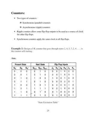
Asynchronous Counter (Ripple Counter) Asynchronous Counter (Ripple Counter) Flip-flops can be connected to get an binary counter, which counts the number of input triggers (clock pulses). Cp=0,a=0,b=0,c=0 Cp=1, A=1, b=0, c=0 Cp=2, a=0,b=1, c=0 Cp=3, a=1,b=1,c=0 Cp=4,a=0,b=0,c=1 Cp=5,a=1,b=0,c=1 Cp=6,a=0,b=1,c=1 Cp=7,a=1,b=1,c=1 Cp=8,a=0,b=0,c=0
Asynchronous Counter (Ripple Counter) Asynchronous Counter (Ripple Counter) The clock pulse drives A. The output of A drives B and the output of B drives C . All the J&K inputs are tied to +Vcc, which means J=K=1. Each flip-flop will toggle with a negative transition at its clock input. This kind of a counter in which output of one flipflop drives the other is called a ripple or asynchronous counter (as trigger moves like a ripple in water). A has to change its state before it can trigger B and B has to change its state before it can trigger C . So the overall propagation delay time is the sum of the individual delays.
Asynchronous Counter (Ripple Counter) Asynchronous Counter (Ripple Counter) Initially all the flip-flops are reset to produce 0 outputs by making use of the clear inputs. The output condition is CBA=000. When the first clock pulse strikes, A changes its states from 0 to 1. Since it is a positive change it will not trigger B . So the output is CBA=001. For the second pulse A changes from 1 to 0. Since it is a negative change it triggers B . So B changes from 0 to 1. Since it is a positive change, it will not trigger C . Now output is CBA=010. For the third pulse A changes from 0 to 1 and it will not trigger B . So the output is CBA=011. In this manner the counter will count up to 111 which is given in the following truth table.
Asynchronous Counter (Ripple Counter) Asynchronous Counter (Ripple Counter) Truth table and waveform From the waveform it is clear that the counter can also be used as a frequency divider. The waveform at A is one half of the clock frequency. B is one fourth of the clock frequency and C is one eighth of the clock frequency. So using three flip-flops we are able to get 8[23] distinct states which can count up to the largest binary number equal to 7 [(23-1) = 7].
Mod Mod- -n counter n counter The total number of counts or discrete states through which a counter can progress is given by 2n, where n is the total number of flip-flops. The total number of states through which a counter can progress is said to be modulus of a counter. The counter which can count through 2, 4, 8, or 16 can be constructed easily by using the proper number of flip-flops. Sometimes it is required to construct a counter which can have modulus other than 2,4,8, or 16. In that case a smaller modulus counter is constructed from a larger modulus counter by skipping states. Such counters are said to have modified counts. The correct number of flip-flops is determined by choosing the lowest natural count (total number of states) which is greater than the desired modified count. For e.g. a mod-7 counter requires three flip-flops since 8 is the lowest natural count greater than the desired modified count of 7.
Mod Mod- -7 Counter (Divide by 7 Counter) 7 Counter (Divide by 7 Counter) Mod-7 counter has only 7 states. The nearest greater natural number for this counter is 23=8. So we should take three flip-flops from which any one of the states can be skipped. The logic diagram of a mod-7 counter which makes use of feedback
Mod Mod- -7 Counter (Divide by 7 Counter) 7 Counter (Divide by 7 Counter)
Mod Mod- -7 Counter (Divide by 7 Counter) 7 Counter (Divide by 7 Counter) The working of the above circuit can be explained as follows. Imagine the circuit without a NAND gate. Now it will count from 000 through l l l . To get a mod-7 Counter, we have to skip 111 state , thereby reducing the count from 8 to 7. This can be done by giving all the outputs (i.e.) A , B and C to a NAND gate, the output of which is given to the clear inputs of all the flip-flops. So when A = B = C = 1, all the flip-flops will be cleared to 0 s immediately as the counter advances to count the next state. Now one state is skipped so that the total number of states becomes equal to 7. Thus a mod-7 counter is obtained (from mod-8).
Mod Mod- -7 Counter (Divide by 7 Counter) 7 Counter (Divide by 7 Counter) truth table truth table
BCD Counter (Mod BCD Counter (Mod- -10 Counter/Decade Counter) 10 Counter/Decade Counter) A BCD Counter counts through 10 different states. It is constructed from a mod-16 counter, by skipping 6 states.
BCD Counter (Mod BCD Counter (Mod- -10 Counter/Decade Counter) 10 Counter/Decade Counter) The six states from 1010 to 1111 are skipped by giving ABCD to clear inputs through a NAND gate, where A=0, B=1, C=0 and D=1 enables the clear inputs and clears all the flip-flops. Since it counts only 10 states, it is called a mod-10 Counter or decade counter.
BCD Counter (Mod BCD Counter (Mod- -10 Counter/Decade Counter) 10 Counter/Decade Counter) truth table truth table Waveform
Synchronous Counter (Parallel Counter) Synchronous Counter (Parallel Counter) The ripple counter is easy to build but there is a limitation of to its highest operating frequency. Here each flip-flop has a delay time and these delays are additive so the propagation delay of the entire counter is the sum of the individual delays. This speed limitation can be overcome by the use of a synchronous or parallel counter. Because here each flip-flop is triggered by the clock and this makes simultaneously transition in all the flip-flops.
Mod Mod- -8 Parallel Binary Counter 8 Parallel Binary Counter
Mod Mod- -8 Parallel Binary Counter 8 Parallel Binary Counter All the three flip-flops are negatively edge triggered and both J&K inputs are tied to +Vcc. The flip-flop A changes state with each negative transition at the clock input. The output of the AND gate (1) goes high whenever the clock is high and A is high. Thus flip-flop B changes state with every other clock. The output of AND gate (2) goes high each time the clock is high and both A are B are high. Thus flip-flop A changes state with every fourth clock. It is found to have eight distinct states which represent a mod-8 parallel counter.
Mod Mod- -8 Parallel Binary Counter 8 Parallel Binary Counter Waveform C B A count 0 0 0 0 0 0 1 1 0 1 0 2 0 1 1 3 1 0 0 4 1 0 1 5 1 1 0 6 1 1 1 7 0 0 0 8


")
")
")
")


")