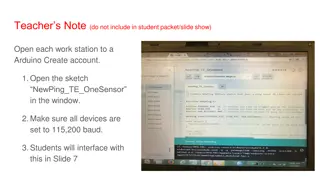
Sensor References and Procedures for NBCRV Operations
This document provides a detailed guide on sensor references, startup, and shutdown procedures for the Nuclear, Biological, and Chemical Reconnaissance Vehicle (NBCRV). It includes information on various sensors, deployment techniques, operating under different conditions, and mission planning considerations. Additionally, specific procedures for starting up and shutting down different sensor components are outlined for efficient operation.

Download Presentation

Please find below an Image/Link to download the presentation.
The content on the website is provided AS IS for your information and personal use only. It may not be sold, licensed, or shared on other websites without obtaining consent from the author. Download presentation by click this link. If you encounter any issues during the download, it is possible that the publisher has removed the file from their server.
E N D
Presentation Transcript
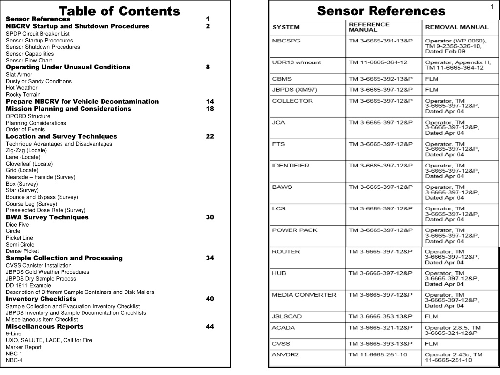
Sensor References Table of Contents Sensor References Sensor References NBCRV Startup and Shutdown Procedures SPDP Circuit Breaker List Sensor Startup Procedures Sensor Shutdown Procedures Sensor Capabilities Sensor Flow Chart Operating Under Unusual Conditions Slat Armor Dusty or Sandy Conditions Hot Weather Rocky Terrain Prepare NBCRV for Vehicle Decontamination Mission Planning and Considerations OPORD Structure Planning Considerations Order of Events Location and Survey Techniques Technique Advantages and Disadvantages Zig-Zag (Locate) Lane (Locate) Cloverleaf (Locate) Grid (Locate) Nearside Farside (Survey) Box (Survey) Star (Survey) Bounce and Bypass (Survey) Course Leg (Survey) Preselected Dose Rate (Survey) BWA Survey Techniques Dice Five Circle Picket Line Semi Circle Dense Picket Sample Collection and Processing CVSS Canister Installation JBPDS Cold Weather Procedures JBPDS Dry Sample Process DD 1911 Example Description of Different Sample Containers and Disk Mailers Inventory Checklists Sample Collection and Evacuation Inventory Checklist JBPDS Inventory and Sample Documentation Checklists Miscellaneous Item Checklist Miscellaneous Reports 9-Line UXO, SALUTE, LACE, Call for Fire Marker Report NBC-1 NBC-4 1 1 1 2 8 14 18 22 30 34 40 44
SPDP Circuit Breaker List (WP 0028) 3 2 NBCRV Startup and Shutdown Procedures (TM 9-2355-326-10-1)
Sensor Shutdown Procedures (WP 0086) Sensor Startup Procedures (WP 0086) 1. Deploy METSMAN Sensor Assembly (WP 0085) 2. Remove all covers as necessary (METSMAN cover, JSLSCAD cover, environmental cover, RWS covers, CBMS probe cover) 3. Open and adjust rear-view mirrors (WP 0004) 4. Install JBPDS BAWS and Collector Stacks (WP 58 & 59) 5. Start engine (WP 0062; vehicle must be placed in high idle (WP 0017) whenever vehicle is stationary and sensor components are operating to ensure adequate power is available) 6. Turn on SPDP (WP 0028) 7. Startup JSLSCAD (WP 0082; ensure CB3, CB4 and CB12 are pushed in on SPDP; turn on ODU within 60 seconds of turning on SPDP; ensure 5 minutes have passed after turning on ODU before turning on the NBCSPG) 8. Startup inverters (WP 0123) 9. Startup C4ISR (WP 0118; CB33 on PDP) 10.Startup DWSS (WP 0078; CB11 & CB19 on SPDP) 11.Startup METSMAN (WP 0085) 12.Startup CBMS II (WP 0074; CB19 on SPDP) 13.Startup AN/UDR-13 (WP 0087; CB6 on SPDP) 14.Startup M88 (WP 0083) 15.Startup AN/VDR-2 (WP 0088) 16.Startup CVSS (WP 0076; CB9 on SPDP) 17.Startup JBPDS (WP 0081; CB18 on SPDP; ensure vehicle is stopped and stacks are installed before turning on. Do not move vehicle until JBPDS is turned off.) 18.Startup NBCSPG (WP 0067; start Surveyor s NBCSPG first; start Cdr sNBCSPG once Surveyor s NBCSPG is at dacsOP login) 4 5 1. Shutdown JBPDS (WP 0081; if operated ensure stack assemblies are removed) - VC 2. Shutdown DWSS (WP 0078) - Surveyor 3. Shutdown AN/VDR-2 (WP 0088) - Surveyor 4. Shutdown M88 (WP 0083) - Surveyor 5. Shutdown JSLSCAD (WP 0082) - Surveyor 6. Pull out circuit breakers 3 and 4 on SPDP Driver 7. Shutdown AN/UDR-13 (WP 0087) - Surveyor 8. Shutdown CBMS II (WP 0074; after shutting off the CBMS, allow the chemical probe to cool down for 20 minutes prior to closing the chemical probe port cover) - Surveyor 9. Shutdown METSMAN (WP 0085) - Surveyor 10.Shutdown CDR s NBCSPG (WP 0067) - VC 11.Shutdown Surveyor s NBCSPG (WP 0067) - Surveyor 12.Shutdown C4ISR (WP 0118) - All 13.Shutdown inverters (WP 0123) - VC 14.Place radio(s) in STANDBY mode - VC 15.Shutdown engine (WP 0137) Driver 16.Open material port - Surveyor 17.Close rear-view mirrors (WP 0004) 18.Reinstall covers (METSMAN cover, JSLSCAD cover, environmental cover, RWS covers, CBMS probe cover) 19.Stow METSMAN sensor (WP 0085)
Sensor Capabilities 7 Sensor Flow Chart 6 Detects, Collects, or Both M22 ACADA Sensor Outputs Limitations Detect JSLSCAD Nerve (G) & Blister (H) Vapors Level of contamination & class of CWA Can detect air vapors within immediate area only CWA CBMS2/DWSS M22 ACADA Collect CVSS Nerve (G) & Blister (H) Vapors Class, type, and relative position of CWA Detects out to 5 kilometers with clear line of sight JSLSCAD Glove & Bottles Detects ground contamination liquids only, 0-5 mph limit when in operation Records data, shows level of contamination & class of CWA All known & unknown CWA Liquids CBMS2/ DWSS Detect Maximum of 12 sample collections, vapor only CVSS All CWA Vapors N/A BWA JBPDS Vehicle must be stopped for min of 65 minutes (20 min to turn on, 25 min to collect one sample, 20 min to turn off) All BWA Vapors (10 at a time depending on installed card) Collect Name of BWA and physical sample JBPDS Dose rate & total accumulated dose Gamma radiation & Beta particles Cannot detect Alpha particles AN/VDR-2 Detect AN/VDR-2 Dose rate & total accumulated dose Cannot detect Alpha or Beta particles Nuclear AN/UDR-13 AN/UDR-13 Gamma radiation N/A Collect Glove Port and Sample Bottles Vehicle must be stopped, difficult to collect All solid and/or liquid CWAs N/A
Slat Armor (WP 0150) 9 8 1. SLAT ARMOR PMCS: With SLAT armor installed on vehicle, perform the following PMCS checks every time you perform(After) PMCS Checks (Volume 5, WP 0850)after completion of daily vehicle operation. 1. Inspect SLAT armor on Front, Left Side, Rear, and Right Side of vehicle for damage and missing hardware. Check for loose bolts and if found, tighten and mark in any manner for future torque application. Notify Field Maintenance of any damage, missing hardware, or tightened bolts requiring torque application. 2. TOWING WITH SLAT ARMOR INSTALLED: Comply with the following requirements and limitations when towing with SLAT Armor installed. 1. NOTE The standard tow bar issued with the Stryker is not acceptable for towing Stryker to Stryker with SLAT armor installed. The new extended split tow bar must be used. 3. TIRE PRESSURE WITH SLAT ARMOR INSTALLED: Comply with the following requirements and limitations for speed and tire pressures when operating a Stryker vehicle equipped with SLAT Armor. 1. For highway (primary road) operations/marches, the Central Tire Inflation System (CTIS) must be turned "OFF". The tires must be inflated to 95 PSI and vehicle speed must not exceed 45 MPH. This maximum speed is for ideal road conditions (i.e. straight sections, no visible obstructions, etc.). Drivers must use common sense and reduce their speed when road conditions are not ideal due to: adverse weather conditions, increased traffic, reduced road width, turns, curves, hill-crests, or any other adverse terrain. Operating Under Unusual Conditions (TM 9-2355-326-10-1)
Slat Armor Cont. (WP 0150) Dusty or Sandy Conditions (WP 0151) 1. Engage eight-wheel drive (WP 0017) if required. 2. Adjust the Central Tire Inflation System (CTIS) (WP 0010) to the Mud and Snow position if required. 3. Stop only on level ground or downgrade to facilitate movement. 4. Allow as much distance as possible between vehicles. 1. NOTE Perform the maintenance procedures identified below to ensure reliable system operation in severe sand and dust environment. 5. Monitor restricted air flow indicator every hour. 6. Check and clean any accumulations of debris from engine grilles at each stop. 7. Keep equipment and operating controls as clean as possible. 8. Protect optical components from etching by removing sand or dust at each stop. 9. Install environmental cover (WP 0052) and sand protection kit and front cover (Volume 2, WP 0157) if vehicle is to be parked for extended periods of time. 11 10 2. For cross country movement requiring greater traction (i.e., soft soil, mud, or snow) or slow speeds, switch the CTIS "ON" and select "HIGHWAY" setting (81 PSI) as required by factors of the mission, enemy troops, terrain, and time available METT-T. With the CTIS "ON" at 81 PSI, a dash up to 40 MPH for a one hour duration is acceptable. 3. For terrain ranging from cross country to secondary roads, the ICV may be driven with the CTIS "ON" at 81 PSI. This is also as required by METT-T and the unit commanders judgment. With resumed extended secondary road movement and as soon as the tactical situation permits, the CTIS should be switched "OFF" and the tires inflated to 95 PSI. 4. UNEXPLODED ORDNANCE (UXO) PROCEDURES: Once the operator knows that a round is lodged in the armor, he should: 1. Immediately evacuate the vehicle. 2. Call for Explosive Ordinance Division (EOD) support. 3. Mark off the area around the vehicle for a safe distance. 4. NEVER try to dislodge the round.
Hot Weather (WP 0152) Hot Weather Cont. (WP 0152) 13 12 1. During hot weather operation, 104 F (40 C) and above, perform the following: 1. Check engine coolant (Volume 5, WP 0871) levels every hour during operations. 2. Check engine oil (Volume 5, WP 0872) levels every hour during operations. 3. Park vehicle in shade or under tarpaulin. If entire vehicle cannot be covered, ensure that weapons and periscopes are covered (WP 0052). 4. Keep vehicle, instruments and weapons clean (Volume 5, WP 0879). Fungus and mildew can grow quickly during humid conditions. 5. Both engine preheat and crew/driver heater (WP 0122) valves should be set to the CLOSED position to prevent heat from entering troop compartment and to permit efficient engine coolant circulation. 6. When temperatures fall below or exceed the operating or storage temperatures, it may be necessary to remove mission equipment from the vehicle. Refer to NBCRV Component Temperature Usage Limits for operating and storage temperatures and NBCRV Equipment Manual References for removal information for NBCRV mission equipment. 2. Observe the above notes when referencing the data in the NBCRV Component Temperature Usage Limits table. Rocky Terrain (WP 0153) 1. Use Central Tire Inflation System (CTIS) (WP 0010) to adjust tire pressure for terrain. 2. Reduce vehicle speed 1. CAUTION The drivetrain and steering components could be damaged if obstacles such as rocks, which exceed the vehicle ground clearance of 16 in. (406 mm), are straddled. Do not straddle obstacles that exceed vehicle ground clearance. Failure to comply may result in damage to equipment. 3. If unable to avoid 16 in. (41 cm) obstacles, position vehicle so that tires drive over them. 4. Follow procedures for cross-country driving (WP 0131).
DECON Preparation Procedure 15 14 1. Power down Mission Equipment, except CCOPS (WP 0086). 2. Power down RWS (WP 0112). Ensure Thermal Imaging Module (TIM) and Visual Imaging Module (VIM) lens covers are installed. 3. Remove Joint Biological Point Detection System (JBPDS) Collector Intake Stack (WP 0059). 4. Remove Biological Agent Warning Sensor (BAWS) Intake Stack (WP 0058). 5. If equipped with BAWS Intake Closure Assembly (ICA), remove BAWS ICA (Volume 5, WP 0885). 6. Cover Joint Services Lightweight Standoff Chemical Agent Detector (JSLSCAD) (1) with three plastic bags (one over the top of the other). Secure plastic bags with tape at base of JSLSCAD (1). 7. Cover Meteorological Sensor (METSMAN) (2) with three plastic bags (one over the top of the other). Secure plastic bags with tape at base of METSMAN(2). 8. Place M88 air inlet valve to Internal (WP 0068). 9. Cover up M88, Chemical Vapor Sampling System (CVSS), and Chemical Biological Mass Spectrometer (CBMS II) air inlet cover (3) with three plastic bags (one over the top of the other). Secure plastic bags with tape at base of air inlet cover (3). 10.Cover Driver's Vision Enhancer (DVE) (4) with three plastic bags (one over the top of the other). Secure plastic bags with tape at base of mounting bracket. 11.Replace five shielding gaskets (Volume 5, WP 0859). 12.Pneumatic system breather and coalescing filter are mandatory replacement items. Notify Field Maintenance for mandatory replacement. 13.Decontaminate vehicle and equipment IAW FM 3-11.5 and unit SOP's. Prepare NBCRV for Vehicle Decontamination (TM 9-2355-326-10-1, WP 0154)
Decontamination Procedure Figures 16 17 Page Intentionally Left Blank
OPORD Key Considerations for Mounted CBRN Recon Mission 18 19 Situation - Friendly Forces - Enemy Forces - Weather (Wind direction/speed) Mission (Stated twice) Execution - Concept of the Operation - Timeline (SP time, Mission Complete time) - Route (Primary/alt routes, checkpoint grids, grid to Button Up Point, order of march, speed, movement formation, vehicle spacing, weapon orientations) - Actions on OBJ (Locate technique, survey technique) - Tasks to Subordinate Units - Coordinating Instructions - Actions on contact - Recovery plan - DECON plan - MOPP Level Sustainment Command and Control - Succession of command - Call signs - Radio frequencies Mission Planning and Considerations (ATP 3-11.37)
20 21 Recon Planning Considerations Actions During Each Phase - - - - - PCCs/PCIs WARNO OPORD Rehearsals Request SP from higher (PAX, VICs, WPN Systems) Troop Leading Procedures 1. Receive the mission 2. Issue WARNO 3. Make a tentative plan 4. Start/begin movement 5. Recon 6. Complete plan 7. Issue OPORD 8. Supervise and refine Planning and SP - - Call up all checkpoints Transition from movement to maneuver when in area of possible enemy contact Movement to BUP - - - - - Confirm Clean Obtain required control samples Button Up Combat Lock Confirm required sensors are turned on and operational Inform higher BUP procedures complete 5 Mounted Movement Formations 1. Column 2. Staggered Column 3. Wedge 4. V Formation 5. Left or Right Echelon Button Up Point - - Conduct Lane, Zig-Zag, Cloverleaf or Grid (refer to pages 15 and 16) Deploy DWSS (unless conducting cloverleaf technique) Report to higher when you have achieved preliminary detection Probe and confirm dirty Collect sample if confirmed dirty Drop DWSS Drop gloves Send reports to higher (NBC 1 and NBC4) Coordinate for DECON - Locate 3 Mounted Movement Techniques 1. Traveling 2. Traveling Overwatch 3. Bounding Overwatch - - - - - - Confirm Dirty Principles of CBRN Operations 1. Ensure continuous CBRN recon 2. Do not keep CBRN assets in reserve 3. Orient on the CBRN recon objective 4. Report information rapidly and accurately 5. Retain freedom of action 6. Gain and maintain CBRN hazard understanding 7. Develop the situation rapidly CBRN Tasks 1. Detect 2. Locate 3. Identify 6. Survey - - Conduct Box, Near side/far side, Star, or Bounce and Bypass (see pages 16 and 17) Send Marker Report (page 47) to higher Survey - - Take the designated dirty route to the DECON site (coordinate with DECON POC if unknown) Follow DECON instructions on page 15 DECON 4. Quantify 5. Collect 7. Mark 8. Report -
Technique Advantages and Disadvantages 23 22 Location and Survey Techniques (ATP 3-11.37, Appendix D)
Zig-Zag (Locate) Lane (Locate) 25 24
Cloverleaf and Grid (Locate) Nearside/Farside & Box (Survey) 27 26
28 Star & Bounce/Bypass (Survey) Course Leg & Preselected Dose Rate (Radiological Survey) 29
Dice Five & Circle 31 30 JBPDS Survey Techniques (ATP 3-11.37, Appendix B)
Picket Line & Semi-Circle Dense Picket 33 32
CVSS Canister Installation (TM 3-6665-393-13&P, WP 0006) 1. Open the CVSU and CSR doors 2. Remove a sealed packaged Sample Canister from the Canister Stowage Container 3. Check the certification date on the outer package of the Sample Canister. Mark Canister on the outside of package as expired if it has been one year from the last day of the month of the certification date and return packaged Canister to Stowage Container. Choose another Sample Canister that is within the acceptable time frame of its certification date. 4. Unpackage Canister. Remove outer packaging and inner packaging. Confirm certification date on Sample Canister label. Dispose of wrapping in accordance with local SOP. 5. Remove the protective metal cap from the Sample Canister QD. Visually examine the Sample Canister male QD for signs of damage. If quick disconnect is bent, damaged or missing, or if the Canister is expired, mark, wrap and stow Canister and repeat Steps 2 - 5 with another packaged Sample Canister. 6. Align the male Sample Canister QD with the female QD fitting in the Pneumatic Unit. 7. Grasp the QD collar and slide sleeve downward and hold. 8. Insert the Sample Canister into the sleeve until it is flush with the QD collar. 9. Release the QD collar and gently pull upward on the Sample Canister to ensure that there is a secure connection. 10. Secure the metal protective cap on the storage clamp 11. Repeat steps 5 through 10 until all three canister bay positions are occupied. 12. Close Canister Stowage Container 13. Perform a canister Reset. Depress and hold the RESET button for at least one second while the CSR is still open. 14. Align the CSR locator pin with corresponding hole in the CSR microswitch mounting plate and close the CSR to initiate BIT. Rotate the CSR knob clockwise until it is tight and activates the CSR microswitch. 15. Wait for BIT to complete. Upon completion of the BIT, the POWER LED and any CAN LED corresponding to installed Sample Canisters will be lit. 16. Close the CVSU door, insert latch in locking mechanism, and rotate latch clockwise until securely fastened 35 34 Sample Collection and Processing
Process JBPDS Dry Collection 1. Put on mask, gloves, and goggles. 2. Retrieve an unused Carrier Card (refer to WP 0034 00). 3. Allow the collection process to complete. 4. At the JBPDS Main Panel screen, touch Change Mode 5. At the Change Mode screen, touch Standby then Apply 6. Bring handle back and rotate turn (advancing to detent). Dry Collection Filter will drop into the Sample Extraction Bottle 7. Open Bottle Shuttle 8. Secure bottle cap onto Sample Extraction Bottle 9. Remove Sample Extraction Bottle 10. If required, install a new Dry Collection Filter and place the system back in Dry Collection Mode. 11. The Dry Collection Filter may contain a collected sample. Follow these steps to process samples: 1. Agitate for one minute by shaking the Sample Extraction Bottle twice per second using an up-and- down motion. 2. Prepare the identification strip of the Carrier Card for inoculation by removing the clear plastic film covering the wells. Forceps may be used if necessary. 3. Remove small cap from the Sample Extraction Bottle. 4. Fill each well of the Carrier Card Assembly. 5. Replace the small cap on the Sample Extraction Bottle and retain. 6. After 15 minutes, the control line and test line (in the event of a positive result) should be clearly visible. Read the results within one minute of the completion of the 15-minute incubation period. 7. When results are known, notify supervisor IAW SOP. The Sample Extraction Bottle with the 10 ml PBS fluid is now the liquid sample. Evacuate samples IAW SOP. 36 37 JBPDS Cold Weather Procedures (Outside Temp <18oF) (TM 3-6665-397-12&P, WP 0028) 1. At the JBPDS Main Panel screen, touch Change Mode 2. When the Change Mode screen opens, touch Standby 3. Touch Apply 4. When the system has entered Standby, install Dry Collection Filter (refer to WP 0029 00). 5. After the Dry Collection Filter is installed, touch Change Mode at the JBPDS Main Panel screen. 6. From Change Mode screen, touch Dry Collection and then Apply 7. A Dry Collection Advisory dialog box will appear displaying Do You Wish To Continue In Dry Collection Mode? . Touch Yes to continue or No to cancel. 1. NOTE The Dry Collection Advisory dialog box reads, Install the Dry Collection Filter... The Dry Collection Filter should already be installed by this step. 8. Put on PPE (mask, goggles, and gloves). 9. Bring handle back and rotate1/4 turn (advancing to detent). Dry Collection Filter will drop into the Sample Extraction Bottle. 10.Open Bottle Shuttle 11.Secure bottle cap onto Sample Extraction Bottle 12.Remove Sample Extraction Bottle 13.Process Dry Collection Filter (refer to WP 0030 00). 14.Discard Sample Extraction Bottle IAW SOP. 15.Remove PPE in the following order: gloves, goggles, and mask. 16.Select Desired Mode of Operation.
Example of DD 1911 Description of Different Sample Containers and Disk Mailers -----------------------------Sample Bottle ----------------------------- Sample bottle containing less than 50 ml of sample, wrapped with lab film, sealed with tamper resistant tape, with absorbent material, placed into double clear plastic bags. Sample bottle and individual clear plastic bags labeled with 17 digit sample ID: *WRITE IN SAMPLE ID # ***SKIP ONE LINE*** Disk mailer sealed with tamper resistant tape, containing 1-ea BIDS incident report, and 1-ea BIO event log. Disk mailer, BIR, and BEL individually labeled with *WRITE IN SAMPLE ID # ----------------------------- Sample Extraction Bottle (SEB) ----------------------------- Sample extraction bottle (SEB) containing a dry collection filter, placed in less than 10 ml of collection fluid, wrapped with lab film, sealed with tamper resistant tape with absorbent material placed into first clear plastic bag, then placed into second clear plastic bag and individual clear plastic bags labeled with *WRITE IN SAMPLE ID # ***SKIP ONE LINE*** Disk mailer sealed with tamper resistant tape, containing 1-ea BIDS incident report, and 1-ea BIO event log. Disk mailer, BIDS incident report, and BIO event log individually labeled with *WRITE IN SAMPLE ID # ----------------------------- Teflon Sample Vial ----------------------------- Teflon sample vial containing less than 50 ml of sample, placed inside of sample rack tubes. Teflon sample vial labeled with *WRITE IN SAMPLE ID # ***SKIP ONE LINE*** Disk mailer sealed with tamper resistant tape, containing 1 each DA Form 1971- 6-R. Disk mailer and DA Form 1971-6-R individually labeled with *WRITE IN SAMPLE ID # ----------------------------- Sample Vial ----------------------------- Sample vial containing less than 10 ml of sample, wrapped with laboratory film, sealed with tamper resistant tape, placed in a 50 ml conical tube with absorbent material placed in a clear bag, with all excess air removed, then placed in another clear plastic bag with all excess air removed. Sample vial, 50 ml conical tube and clear plastic bag labeled with *WRITE IN SAMPLE ID # ***SKIP ONE LINE*** Disk mailer sealed with tamper resistant tape, containing 1-ea BIDS incident report, and 1-ea BIO event log. Disk mailer, BIR, and BEL individually labeled with *WRITE IN SAMPLE ID # ----------------------------- Sample Canister ----------------------------- Sample canister containing less than 300 ml of sample, wrapped with lab film, sealed with tamper resistant tape, with absorbent material placed into first clear plastic bag, then placed into second clear plastic bag. Sample canister and individual clear plastic bags labeled with *WRITE IN SAMPLE ID # ***SKIP ONE LINE*** Disk mailer sealed with tamper resistant tape, containing 1-ea DA Form 1971-6- R. Disk mailer and DA Form 1971-6-R individually labeled with *WRITE IN SAMPLE ID # 39 38 Unit Designation (Ex: A CO, 1st BN) Grid of sample collection location Team ID (Ex: A TM, 1st PLT, A CO) Description of sample taken Description of disk mailer Sample ID # Sample ID # 1 1 2 1 Transfer Date Unit of transfer recipient Name, grade and title of person taking sample Signature of transfer recipient Destination of sample and DTG Name, grade and title of transfer recipient Grid of transfer and reason
Sample Collection & Evacuation Inventory Checklist per VIC 41 40 Collection/Marking Items Min. Required Glove for Glove Port 2 DWSS Wheels 10 Marker bases, stems, and flags 12 each Roll of Duct Tape 1 Teflon Sample Vials 16 CVSS Canisters 12 CBMS2 Probe Membrane 2 CBMS2 Probe Union Nut 2 Evacuation Items Min. Required Inventory Checklists for PCCs and PCIs Conical Tube 1 8x8 Baggies 4 10x10 Baggies 4 Cheese Cloth 4 Squares of Parafilm 15 Tweezers 1 Scissors 1 Twisty/Zip Ties 15 Rolls of Tamper Resistant Tape 1 Label Stickers 5 PPE (Latex Gloves, Goggles, Mask) 2 each Printer Paper 20 Sheets Disk Mailers 4 CDs/Flash Drives 4 All Required Paperwork (See next) 5 copies of each
JBPDS Inventory and Sample Documentation Checklists Miscellaneous Item Checklist 43 42 JBPDS Consumables Minimum Required Miscellaneous Items Minimum Required Sample Vials 4 Fuel Cans 4 Sample Bottles 2 MRE Boxes 1 Detergent Bottle 1 (min full) Water Jugs 1 DI Water Bottle 1 (min full) Ammunition METT-TC PBS Bottle 1 (min full) Map 1 Waste Bottle 1 Map Marker Set 1 Carrier Box Assembly 1 Protractor 1 Control Carrier Card 1 Sample Extraction Bottle 1 Dry Collection Filter 4 Forceps 1 Pipette 1 Required Forms Purpose BIDS Incident Report Document details of a biological incident Biological Event Log Document details of a chemical incident DA 1971-6-R DD 1911 or DA 4137 Show chain of custody DA 1594 (Staff Duty Log) Document all actions taken
9-Line Medevac 45 44 Miscellaneous Reports
UXO, SALUTE, LACE, CFF Marker Report (CBRN 5) Marker 1: CWA, BWA, or RAD DTG__________________ Type__________________ MGRS________________ Marker 2: CWA, BWA, or RAD DTG__________________ Type__________________ MGRS________________ Marker 3: CWA, BWA, or RAD DTG__________________ Type__________________ MGRS________________ Marker 4: CWA, BWA, or RAD DTG__________________ Type__________________ MGRS________________ Marker 5: CWA, BWA, or RAD DTG__________________ Type__________________ MGRS________________ Marker 6: CWA, BWA, or RAD DTG__________________ Type__________________ MGRS________________ 47 46 Marker 7: CWA, BWA, or RAD DTG__________________ Type__________________ MGRS________________ Marker 8: CWA, BWA, or RAD DTG__________________ Type__________________ MGRS________________ Marker 9: CWA, BWA, or RAD DTG__________________ Type__________________ MGRS________________ Marker 10: CWA, BWA, or RAD DTG__________________ Type__________________ MGRS________________ Marker 11: CWA, BWA, or RAD DTG__________________ Type__________________ MGRS________________ Marker 12: CWA, BWA, or RAD DTG__________________ Type__________________ MGRS________________
NBC-1 NBC-4 49 48


")
")
")


")
")