JCB VMS55 Mini Road Roller Service Repair Manual Instant Download
Please open the website below to get the complete manualnn//

Download Presentation

Please find below an Image/Link to download the presentation.
The content on the website is provided AS IS for your information and personal use only. It may not be sold, licensed, or shared on other websites without obtaining consent from the author. Download presentation by click this link. If you encounter any issues during the download, it is possible that the publisher has removed the file from their server.
E N D
Presentation Transcript
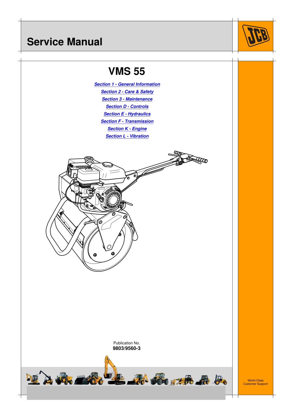
Service Manual VMS 55 Section 1 - General Information Section 2 - Care & Safety Section 3 - Maintenance Section D - Controls Section E - Hydraulics Section F - Transmission Section K - Engine Section L - Vibration Publication No. 9803/9560-3 World Class Customer Support Copyright 2004 JCB SERVICE. All rights reserved. No part of this publication may be reproduced, stored in a retrieval system, or transmitted in any form or by any other means, electronic, mechanical, photocopying or otherwise, without prior permission from JCB SERVICE. Issued by JCB Technical Publications, JCB Aftermarket Training, Woodseat, Rocester, Staffordshire, ST14 5BW, England. Tel +44 1889 591300 Fax +44 1889 591400
Section 1 - General Informnation Contents Introduction About this Manual .....................................................................................1 - 1 Identifying Your Machine ..........................................................................1 - 2 Component Identification Plates ...............................................................1 - 3 Page No. Torque Settings Zinc Plated Fasteners and Dacromet Fasteners ......................................1 - 5 Vibromax Specific Torque Settings ...........................................................1 - 9 Hydraulic Connections ............................................................................1 - 11 Service Consumables Sealing and Retaining Compounds ........................................................1 - 15 1 - i 1 - i
Section 1 - General Information Introduction About this Manual Introduction About this Manual Machine Model and Serial Number Section Numbering T11-005 This manual provides information for the following model(s) in the JCB machine range: The manual is compiled in sections, the first three are numbered and contain information as follows: VMS 55 from SN 1401000 to SN 1401999 General Information - includes torque settings and service tools. Care and Safety - includes warnings and cautions pertinent to aspects of workshop procedures etc. Maintenance - includes service schedules and recommended lubricants for all the machine. 1 Using the Service Manual 2 T11-004 This publication is designed for the benefit of JCB Distributor Service Engineers who are receiving, or have received, training by JCB Technical Training Department. 3 These personnel should have a sound knowledge of workshop practice, safety procedures, and general techniques associated with the maintenance and repair of hydraulic earthmoving equipment. The remaining sections are alphabetically coded and deal with Dismantling, Overhaul etc. of specific components, for example: Attachments Body and Framework, etc. A B The illustrations in this publication are for guidance only. Where the machines differ, the text and/or the illustration will specify. Section contents, technical data, circuit descriptions, operation descriptions etc. are inserted at the beginning of each alphabetically coded section. General warnings in Section 2 are repeated throughout the manual, as well as specific warnings. Read all safety statements regularly, so you do not forget them. Units of Measurement Renewal of oil seals, gaskets, etc., and any component showing obvious signs of wear or damage is expected as a matter of course. It is expected that components will be cleaned and lubricated where appropriate, and that any opened hose or pipe connections will be blanked to prevent excessive loss of hydraulic fluid and ingress of dirt. T1-001_2 In this publication, the S.I. system of units is used. For example, liquid capacities are given in litres. The Imperial units follow in parentheses ( ) eg 28 litres (6 gal). Left Side, Right Side Where a torque setting is given as a single figure it may be varied by plus or minus 3%. Torque figures indicated are for dry threads, hence for lubricated threads may be reduced by one third. In this manual, 'left' and 'right' mean your left and right when you are standing behind the machine, holding the hand grips. Cross References The manufacturer's policy is one of continuous improvement. The right to change the specification of the machine without notice is reserved. No responsibility will be accepted for discrepancies which may occur between specifications of the machine and the descriptions contained in this publication. T1-004_2 In this publication, page cross references are made by presenting the subject title printed in bold, italic and underlined. It is preceeded by the 'go to' symbol. The number of the page upon which the subject begins, is indicated within the brackets. For example: K References ( T T 1-1). K Cross Finally, please remember above all else safety must come first! 1 - 1 1 - 1 9803/9560-3
Section 1 - General Information Introduction Identifying Your Machine Identifying Your Machine Machine Identification Plate Typical Product Identification Number (PIN) Your machine has an identification plate mounted as shown. K K Fig 1. ( T T 1-2). The serial numbers of the machine and its major units are stamped on the plate. JBP 1 VMS55 2 C 3 7 4 1410000 5 World Manufacturer Identification (3 Digits) 1 The serial number of each major unit is also stamped on the unit itself. K K Fig 2. ( T T 1-3). If a major unit is replaced by a new one, the serial number on the identification plate will be wrong. Either stamp the new number of the unit on the identification plate, or simply stamp out the old number. This will prevent the wrong unit number being quoted when replacement parts are ordered. Machine Model (5 Digits) 2 VMS55 Randomly Generated Check Letter (1 Digit) 3 Year of Manufacture (1 Digit): 4 The machine and engine serial numbers can help identify exactly the type of equipment you have. 7 = 2007 8 = 2008 9 = 2009 Machine Serial Number (7 Digits) 5 Each machine has a unique serial number. Fig 1. 1 - 2 1 - 2 9803/9560-3
https://www.ebooklibonline.com Hello dear friend! Thank you very much for reading. Enter the link into your browser. The full manual is available for immediate download. https://www.ebooklibonline.com
Section 1 - General Information Introduction Component Identification Plates Component Identification Plates Component Identification Plates Fig 2. Engine serial number A 1 - 3 1 - 3 9803/9560-3
Section 1 - General Information Torque Settings Zinc Plated Fasteners and Dacromet Fasteners T11-002 Introduction Bolts and Screws Some external fasteners on JCB machines are manufactured using an improved type of corrosion resistant finish. This type of finish is called Dacromet and replaces the original Zinc and Yellow Plating used on earlier machines. Use the following torque setting tables only where no torque setting is specified in the text. Note: Dacromet fasteners are lubricated as part of the plating process, do not lubricate. The two types of fasteners can be readily identified by colour and part number suffix. K ( T T 1-5). Torque settings are given for the following conditions: K Table 1. Fastener Types Condition 1 Table 1. Fastener Types Colour Un-lubricated fasteners Zinc fasteners Yellow plated fasteners Fastener Type Zinc and Yellow Dacromet Part No. Suffix Golden finish 'Z' (e.g. 1315/3712Z) Condition 2 Mottled silver finish 'D' (e.g. 1315/3712D) Zinc flake (Dacromet) fasteners Lubricated zinc and yellow plated fasteners Where there is a natural lubrication. For example, cast iron components Note: As the Dacromet fasteners have a lower torque setting than the Zinc and Yellow fasteners, the torque figures used must be relevant to the type of fastener. Note: A Dacromet bolt should not be used in conjunction with a Zinc or Yellow plated nut, as this could change the torque characteristics of the torque setting further. For the same reason, a Dacromet nut should not be used with a Zinc or Yellow plated bolt. Verbus Ripp Bolts Note: All bolts used on JCB machines are high tensile and must not be replaced by bolts of a lesser tensile specification. Fig 1. Note: Dacromet bolts, due to their high corrosion resistance are used in areas where rust could occur. Dacromet bolts are only used for external applications. They are not used in applications such as gearbox or engine joint seams or internal applications. Torque settings for these bolts are determined by the application. Refer to the relevant procedure for the required settings. 1 - 5 1 - 5 9803/9560-3
Section 1 - General Information Torque Settings Zinc Plated Fasteners and Dacromet Fasteners Table 2. Torque Settings - UNF Grade 'S' Fasteners Hexagon (A/F) in. Nm 7/16 11.2 1/2 22.3 9/16 40.0 5/8 64.0 3/4 98.00 13/16 140.0 15/16 196.0 1 1/8 343.0 1 15/16 547.0 1 1/2 814.0 1 7/8 1181.0 2 1/4 1646.0 Bolt Size Condition 1 kgf m 1.1 2.3 4.1 6.5 10.0 14.3 20.0 35.0 55.8 83.0 120.4 167.8 Condition 2 kgf m 1.0 2.0 3.7 5.8 9.0 12.8 18.0 31.5 50.2 74.6 108.4 151.0 in. 1/4 5/16 3/8 7/16 1/2 9/16 5/8 3/4 7/8 1 1 1/8 1 1/4 mm 6.3 7.9 9.5 11.1 12.7 14.3 15.9 19.0 22.2 25.4 31.7 38.1 lbf ft 8.3 16.4 29.5 47.2 72.3 103.2 144.6 253.0 403.4 600.4 871.1 1214.0 Nm 10.0 20.0 36.0 57.0 88.0 126.0 177.0 309.0 492.0 732.0 1063.0 1481.0 lbf ft 7.4 14.7 26.5 42.0 64.9 92.9 130.5 227.9 362.9 539.9 784.0 1092.3 Table 3. Torque Settings - Metric Grade 8.8 Fasteners Hexagon (A/F) Bolt Size Condition 1 Condition 2 ISO Metric Thread M5 M6 M8 M10 M12 M16 M20 M24 M30 M36 mm 5 6 8 10 12 16 20 24 30 36 mm 8 10 13 17 19 24 30 36 46 55 Nm 5.8 9.9 24.0 47.0 83.0 205.0 400.0 690.0 1372.0 2399.0 kgf m 0.6 1.0 2.4 4.8 8.5 20.9 40.8 70.4 139.9 244.6 lbf ft 4.3 7.3 17.7 34.7 61.2 151.2 295.0 508.9 1011.9 1769.4 Nm 5.2 9.0 22.0 43.0 74.0 184.0 360.0 621.0 1235.0 2159.0 kgf m 0.5 0.9 2.2 4.4 7.5 18.8 36.7 63.3 125.9 220.0 lbf ft 3.8 6.6 16.2 31.7 54.6 135.7 265.5 458.0 910.9 1592.4 1 - 6 1 - 6 9803/9560-3
Section 1 - General Information Torque Settings Zinc Plated Fasteners and Dacromet Fasteners Table 4. Metric Grade 10.9 Fasteners Hexagon (A/F) Bolt Size Condition 1 Condition 2 ISO Metric Thread M5 M6 M8 M10 M12 M16 M20 M24 M30 M36 mm 5 6 8 10 12 16 20 24 30 36 mm 8 10 13 17 19 24 30 36 46 55 Nm 8.1 13.9 34.0 67.0 116.0 288.0 562.0 971.0 1930.0 3374.0 kgf m 0.8 1.4 3.5 6.8 11.8 29.4 57.3 99.0 196.8 344.0 lbf ft 6.0 10.2 25.0 49.4 85.5 212.4 414.5 716.9 1423.5 2488.5 Nm 7.3 12.5 30.0 60.0 104.0 259.0 506.0 874.0 1737.0 3036.0 kgf m 0.7 1.3 3.0 6.1 10.6 26.4 51.6 89.1 177.1 309.6 lbf ft 5.4 9.2 22.1 44.2 76.7 191.0 373.2 644.6 1281.1 2239.2 Table 5. Metric Grade 12.9 Fasteners Hexagon (A/F) Bolt Size Condition 1 Condition 2 ISO Metric Thread M5 M6 M8 M10 M12 M16 M20 M24 M30 M36 mm 5 6 8 10 12 16 20 24 30 36 mm 8 10 13 17 19 24 30 36 46 55 Nm 9.8 16.6 40.0 80.0 139.0 345.0 674.0 1165.0 2316.0 4049.0 kgf m 1.0 1.7 4.1 8.1 14.2 35.2 68.7 118.8 236.2 412.9 lbf ft 7.2 12.2 29.5 59.0 102.5 254.4 497.1 859.2 1708.2 2986.4 Nm 8.8 15.0 36.0 72.0 125.0 311.0 607.0 1048.0 2084.0 3644.0 kgf m 0.9 1.5 3.7 7.3 12.7 31.7 61.9 106.9 212.5 371.6 lbf ft 6.5 11.1 26.5 53.1 92.2 229.4 447.7 773.0 1537.1 2687.7 1 - 7 1 - 7 9803/9560-3
Section 1 - General Information Torque Settings Zinc Plated Fasteners and Dacromet Fasteners Table 6. Torque Settings - Rivet Nut Bolts/Screws Bolt Size ISO Metric Thread mm M3 3 M4 4 M5 5 M6 6 M8 8 M10 10 M12 12 Nm 1.2 3.0 6.0 10.0 24.0 48.0 82.0 kgf m 0.1 0.3 0.6 1.0 2.5 4.9 8.4 lbf ft 0.9 2.0 4.5 7.5 18.0 35.5 60.5 Table 7. Torque Settings - Internal Hexagon Headed Cap Screws (Zinc) Bolt Size ISO Metric Thread M3 2.0 M4 6.0 M5 11.0 M6 19.0 M8 46.0 M10 91.0 M12 159.0 M16 395.0 M18 550.0 M20 770.0 M24 1332.0 Nm kgf m 0.2 0.6 1.1 1.9 4.7 9.3 16.2 40.0 56.0 79.0 136.0 lbf ft 1.5 4.5 8.0 14.0 34.0 67.0 117.0 292.0 406.0 568.0 983.0 1 - 8 1 - 8 9803/9560-3
Section 1 - General Information Torque Settings Vibromax Specific Torque Settings Vibromax Specific Torque Settings Where no special torque data is specified, the following standard torque figures should be applied. Table 8. Standard Torque Specifications +/- 10% GRADE 8.8 Nm lb/ft 5.5 4 9 6.6 22.5 16.5 44 32 77.5 57 120 88 190 140 260 192 370 273 520 500 369 640 471 950 702 1300 955 GRADE 10.9 Nm 7.5 12.5 31.5 62 110 170 265 365 GRADE 12.9 Nm 9 15 36 75 130 210 320 435 620 840 1080 1620 2160 SIZE 5mm 6mm 8mm 10mm 12mm 14mm 16mm 18mm 20mm 22mm 24mm 27mm 30mm lb/ft 5.5 9.2 23 45 81 125 195 269 383 516 665 996 1328 lb/ft 6.6 11 26.5 55 95 155 236 320 457 619 796 1195 1593 700 900 1350 1800 Table 9. Nuts for Tubes and Hoses DIAMETER AND PITCH 16mm X 1.5 18mm X 1.5 20mmX 1.45 24mm X 1.5 Nm 20 35 45 60 lb/ft 14.5 26 33.2 44 Table 10. Fittings, Connections and Plugs DIAMETER AND PITCH 10mm X 1.5 12mm X 1.5 14mm X 1.5 16mm X 1.5 18mm X 1.5 22mm X 1.5 27mm X 1.5 33mm X 1.5 42mm X 1.5 Nm 20 35 45 60 70 100 200 280 380 lb/ft 14.5 26 33.2 44 51 73 147 207 281 1 - 9 1 - 9 9803/9560-3
Suggest: If the above button click is invalid. Please download this document first, and then click the above link to download the complete manual. Thank you so much for reading
Section 1 - General Information Torque Settings Vibromax Specific Torque Settings Table 11. Flanges Nm 28 55 90 145 230 DIAMETER AND PITCH 8mm X 1.5 10mm X 1.5 12mm X 1.75 14mm X 2 15mm X 2 lb/ft 21 41 67 107 170 1 - 10 1 - 10 9803/9560-3
https://www.ebooklibonline.com Hello dear friend! Thank you very much for reading. Enter the link into your browser. The full manual is available for immediate download. https://www.ebooklibonline.com