JCB VIBROMAX W1500 Trench Roller Service Repair Manual Instant Download 1
Please open the website below to get the complete manualnn//

Download Presentation

Please find below an Image/Link to download the presentation.
The content on the website is provided AS IS for your information and personal use only. It may not be sold, licensed, or shared on other websites without obtaining consent from the author. Download presentation by click this link. If you encounter any issues during the download, it is possible that the publisher has removed the file from their server.
E N D
Presentation Transcript
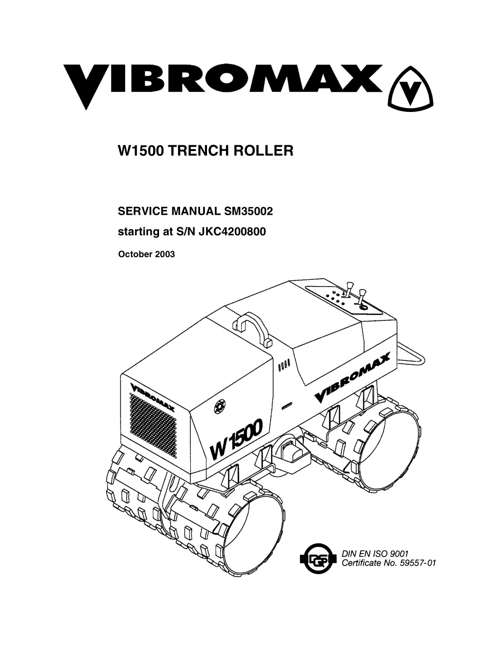
W1500 TRENCH ROLLER SERVICE MANUAL SM35002 starting at S/N JKC4200800 October 2003
CALIFORNIA Proposition 65 Warning Diesel engine exhaust and some of its constituents are known to the State of California to cause cancer, birth defects, and other reproductive harm.
SECTION ONE GENERAL INFORMATION MACHINE IDENTIFICATION................................................................ 1 - 2 MACHINE DESCRIPTION.................................................................... 1 - 3 MACHINE SERIAL NUMBERS............................................................. 1 - 4 COMPONENT IDENTIFICATION ......................................................... 1 - 5 SAFETY ................................................................................................ 1 - 6 SPARK ARRESTER ..................................................................1 - 6 PERSONAL................................................................................1 - 6 MACHINE OPERATION.............................................................1 - 7 MAINTENANCE .........................................................................1 - 9 GENERAL INFORMATION.................................................................1 - 10 STANDARD TORQUE DATA.............................................................. 1 - 11 METRIC/USA CONVERSIONS........................................................... 1 - 13 MACHINE SPECIFICATIONS............................................................. 1 - 14 FLUID CAPACITY............................................................................... 1 - 14 ENGINE DATA.........................................................................1 - 15 OPERATING DATA..................................................................1 - 15 DIESEL FUEL SPECIFICATION......................................................... 1 - 16 ENGINE OIL SPECIFICATION........................................................... 1 - 17 MACHINE CONTROLS, MANUAL...................................................... 1 - 18 MACHINE CONTROLS, WITH REMOTE........................................... 1 - 20 REMOTE BATTERY CHARGER ........................................................1 - 22 STARTING THE ENGINE ................................................................... 1 - 23 PARKING BRAKE............................................................................... 1 - 23 MACHINE OPERATION...................................................................... 1 - 24 PARKING............................................................................................1 - 24 TURNING OFF THE ENGINE............................................................. 1 - 24 MAINTENANCE SCHEDULE.............................................................. 1 - 25 As Required..............................................................................1 - 25 Every 10 hours or daily.............................................................1 - 25 Every 100 hours of operation ...................................................1 - 25 Every 150 hours .......................................................................1 - 25 Every 500 hours of operation ...................................................1 - 26 Every 1000 hours of operation or annually...............................1 - 26 SECTION TWO ENGINE ENGINE OVERHAUL............................................................................ 2 - 2 KUBOTA ENGINE WARRANTY ........................................................... 2 - 2 Oil and filter change .............................................................................. 2 - 5 AIR FILTER SYSTEM........................................................................... 2 - 6 Dust collector..............................................................................2 - 6 Replacing the filter elements......................................................2 - 7 1
Cleaning the primary filter element.............................................2 - 7 ENGINE COOLING SYSTEM............................................................... 2 - 8 Inspection...................................................................................2 - 8 Check coolant level ....................................................................2 - 8 Cleaning .....................................................................................2 - 9 Filling the cooling system ...........................................................2 - 9 ENGINE FUEL SYSTEM..................................................................... 2 - 10 Venting the fuel system............................................................2 - 11 Replacing the fuel filter.............................................................2 - 11 SECTION THREE ELECTRICAL CIRCUITS ELECTRICAL SYSTEM ........................................................................ 3 - 2 Battery........................................................................................3 - 2 Battery fluid level........................................................................3 - 2 Fuses and Relays.......................................................................3 - 3 UNDERSTANDING ELECTRICAL SCHEMATICS .............................. 3 - 5 UNDERSTANDING RELAYS................................................................ 3 - 8 ENGINE ELECTRICAL CIRCUITS ..................................................... 3 - 11 UNDERSTANDING BATTERIES........................................................3 - 12 UNDERSTANDING ALTERNATORS.......................................3 - 14 STARTER SYSTEM DIAGNOSTICS.................................................. 3 - 18 MACHINE ELECTRICAL CIRCUITS................................................... 3 - 21 ELECTRICAL LAYOUT....................................................................... 3 - 22 ELECTRICAL SCHEMATICS.............................................................. 3 - 26 WIRE HARNESS 5731/82110............................................................. 3 - 30 WIRE CHART 5731/82110.................................................................. 3 - 31 WIRE HARNESS 5731/82505............................................................. 3 - 32 WIRE CHART 5731/82505.................................................................. 3 - 33 WIRE HARNESS 5731/82121............................................................. 3 - 34 WIRE CHART 5731/82121.................................................................. 3 - 35 WIRE HARNESS 5731/82105............................................................. 3 - 37 WIRE CHART 5731/82105.................................................................. 3 - 38 WIRE HARNESS 5731/82175............................................................. 3 - 40 SECTION FOUR HYDRAULIC SYSTEMS IDENTIFYING HYDRAULIC COMPONENTS....................................... 4 - 2 SUCTION LINES................................................................................... 4 - 3 PROPULSION SYSTEM DRAWINGS.................................................. 4 - 4 PROPULSION SYSTEM FUNCTION.........................................4 - 7 VIBRATION SYSTEM DRAWINGS ...................................................... 4 - 8 HIGH SPEED TRAVEL DRAWINGS .................................................. 4 - 10 VIBRATION SYSTEM FUNCTION...........................................4 - 13 2
https://www.ebooklibonline.com Hello dear friend! Thank you very much for reading. Enter the link into your browser. The full manual is available for immediate download. https://www.ebooklibonline.com
HIGH SPEED TRAVEL FUNCTION.........................................4 - 13 BRAKE SYSTEM DRAWINGS............................................................ 4 - 14 DRAIN LINE DRAWINGS ................................................................... 4 - 16 HYDRAULIC TEST PORTS................................................................4 - 18 HYDRAULIC SCHEMATIC .................................................................4 - 20 SECTION FIVE CHASSIS LOWER FRAME.................................................................................... 5 - 2 UPPER FRAME .................................................................................... 5 - 3 VIBRATION SHAFT.............................................................................. 5 - 4 VIBRATION SYSTEM........................................................................... 5 - 6 Oil change ..................................................................................5 - 6 3
SECTION ONE GENERAL INFORMATION 1 - 1
SM35002 - SECTION ONE GENERAL INFORMATION MACHINE IDENTIFICATION The terms left , right , front , rear used in this manual refer to the sides of the machine as seen from the operator s position at the controls. 1) 2) 3) 4) Front Rear Right Left 1 - 2
SM35002 - SECTION ONE GENERAL INFORMATION MACHINE DESCRIPTION The hydrostatic drive system is designed for two ground speeds. The hydrostatic drive system consists of two gear pumps, left and right drum drive motors with hydraulic brakes, and the system control valves. The left side drums are independently operated from the right side. This feature allows the machine to be steered. The Vibromax Model W1500 Trench Roller is a 1.5 metric ton tandem drum roller with hydrostatic propulsion and a hydrostatic vibratory system. The machine is available with either a 24.8 inch (630 mm) or a 33.5 inch (850 mm) drum. All models include pressure test ports for quick and easy diagnostics of the various hydraulic systems. The machines can be ordered with manual or remote controls. Power is provided by a 61 cubic inch (1000 cc) Kubota, three cylinder water cooled diesel engine, Model D1005/-BB-EC, rated at 22.5 hp (16.8 kW) at 3000 RPM. Remote controlled units are operated either manually or by using the radio controlled remote system. Remote controlled machines are equipped with an auxiliary battery for the remote controller and a battery charger to insure a fully charged battery is always available. The W1500 trench roller operates at a vibration frequency of 1860 vibrations per minute (31 Hz). The machine is designed with a single vibratory shaft mounted between the front and rear drum. 1 - 3
SM35002 - SECTION ONE GENERAL INFORMATION MACHINE SERIAL NUMBERS Enter the machine and components serial numbers on the following lines. When ordering spare parts or requesting information on the machine, have these numbers available for your dealer. Make a copy of these numbers and keep them in a safe place. If the machine is stolen, these numbers should be made available to the investigating authorities. #1 Model and Serial Number #2 Engine ID. Numbers #3 Remote Control Serial Number (numbers located on control under remote battery) 1 - 4
SM35002 - SECTION ONE GENERAL INFORMATION COMPONENT IDENTIFICATION 1 drum 13 drum motor 2 drum scraper 14 drum motor with brake 3 diesel engine 15 lifting point 4 radiator 16 safety strap 5 vibratory shaft 17 engine oil dipstick 6 fuel tank 18 engine hood 7 hydraulic oil tank 19 rear hood 8 battery 20 control panel cover 9 instrument panel 21 remote transmitter (option) 10 emergency stop bar 22 remote receiver (option) 11 platform buffers 23 antenna for receiver (option) 12 air filter 24 remote actuation switch (option) 1 - 5
Suggest: If the above button click is invalid. Please download this document first, and then click the above link to download the complete manual. Thank you so much for reading
SM35002 - SECTION ONE GENERAL INFORMATION SAFETY The information in this manual does not replace any safety rules and laws used in your area. Before operating this machine, learn the rules and laws for your area and make sure your machine has the correct equipment according to these rules and regulations. Before starting the engine study the operator s manual. Know the location and function of all machine controls. Clear the area of other persons before you start the engine. Check all controls in a safe area before you operate the machine. Understand the limits of the machine. Do not try to do too much too fast. Keep the machine under control at all times. SPARK ARRESTER NOTE: Rules or laws in some areas may require that this machine be equipped with a spark arrester or spark arrester muffler. Check the rules or laws in your area. PERSONAL Loose clothing and jewelry can cause an accident. Do not wear loose clothing or jewelry that can catch on controls, etc. Do wear safety shoes, hard hat, heavy gloves, etc. when required for your protection. Foreign materials and loose objects on the machine can cause accidents and injury. Keep the machine clear at all times. Know and understand the arrangements for movement of trucks, machines, and per- sons on your job site. Understand and follow the instructions of flagmen, road signs, or signals. Check machine controls for proper operation prior to starting the machine. A fire can cause injury or death. Always have a fire extinguisher on the job site near the machine. Make sure the fire extinguisher is serviced according to the manufacturer s 1 - 6
https://www.ebooklibonline.com Hello dear friend! Thank you very much for reading. Enter the link into your browser. The full manual is available for immediate download. https://www.ebooklibonline.com