JCB VIBROMAX W1500 Trench Roller Service Repair Manual Instant Download
Please open the website below to get the complete manualnn//

Download Presentation

Please find below an Image/Link to download the presentation.
The content on the website is provided AS IS for your information and personal use only. It may not be sold, licensed, or shared on other websites without obtaining consent from the author. Download presentation by click this link. If you encounter any issues during the download, it is possible that the publisher has removed the file from their server.
E N D
Presentation Transcript
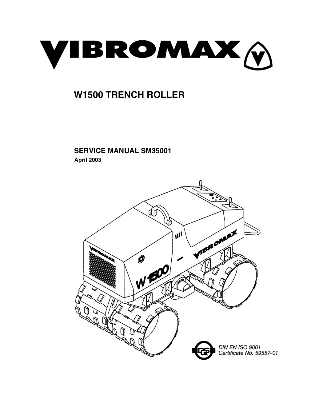
W1500 TRENCH ROLLER SERVICE MANUAL SM35001 April 2003
CALIFORNIA Proposition 65 Warning Diesel engine exhaust and some of its constituents are known to the State of California to cause cancer, birth defects, and other reproductive harm.
SECTION ONE GENERAL INFORMATION MACHINE DESCRIPTION ..............................................................................1 - 3 MACHINE SERIAL NUMBERS .......................................................................1 - 4 COMPONENT IDENTIFICATION ...................................................................1 - 5 SAFETY ..........................................................................................................1 - 6 SPARK ARRESTER .................................................................................1 - 6 PERSONAL ...............................................................................................1 - 6 MACHINE OPERATION ............................................................................1 - 7 MAINTENANCE .........................................................................................1 - 9 GENERAL INFORMATION ...........................................................................1 - 10 CLEANING .........................................................................................1 - 10 INSPECTION .....................................................................................1 - 10 BEARINGS .........................................................................................1 - 10 NEEDLE BEARINGS .........................................................................1 - 10 GEARS ...............................................................................................1 - 10 OIL SEALS, O-RINGS, & GASKETS .................................................1 - 10 SHAFTS .............................................................................................1 - 11 SERVICE PARTS ...............................................................................1 - 11 LUBRICATION ...................................................................................1 - 11 STANDARD TORQUE DATA .......................................................................1 - 11 METRIC/USA CONVERSIONS ....................................................................1 - 13 MACHINE SPECIFICATIONS .......................................................................1 - 14 FLUID CAPACITY .........................................................................................1 - 14 ENGINE DATA ........................................................................................1 - 15 OPERATING DATA .................................................................................1 - 15 DIESEL FUEL SPECIFICATION ...................................................................1 - 16 ENGINE OIL SPECIFICATION .....................................................................1 - 17 MACHINE CONTROLS, MANUAL ................................................................1 - 18 MACHINE CONTROLS, WITH REMOTE .....................................................1 - 20 REMOTE BATTERY CHARGER ..................................................................1 - 22 STARTING THE ENGINE .............................................................................1 - 23 PARKING BRAKE .........................................................................................1 - 23 MACHINE OPERATION ...............................................................................1 - 24 PARKING ......................................................................................................1 - 24 TURNING OFF THE ENGINE .......................................................................1 - 24 MAINTENANCE SCHEDULE .......................................................................1 - 25 As Required .............................................................................................1 - 25 Every 10 hours or daily ............................................................................1 - 25 Every 100 hours of operation ...................................................................1 - 25 Every 150 hours .......................................................................................1 - 25 Every 500 hours of operation ...................................................................1 - 26 Every 1000 hours of operation or annually ..............................................1 - 26
SECTION TWO ENGINE ENGINE OVERHAUL ......................................................................................2 - 2 KUBOTA ENGINE WARRANTY .....................................................................2 - 2 SECTION THREE ELECTRICAL CIRCUITS UNDERSTANDING ELECTRICAL SCHEMATICS ........................................3 - 3 UNDERSTANDING RELAYS ..........................................................................3 - 6 VIBROMAX RELAYS ...........................................................................3 - 7 ENGINE ELECTRICAL CIRCUITS .................................................................3 - 9 UNDERSTANDING BATTERIES ..................................................................3 - 10 BATTERY DIAGNOSTICS .................................................................3 - 11 UNDERSTANDING ALTERNATORS ......................................................3 - 12 CHARGING SYSTEM DIAGNOSTICS ..............................................3 - 13 VOLTAGE CHECKS AT ALTERNATOR ...........................................3 - 13 SYSTEM LEAKAGE ...........................................................................3 - 14 CIRCUIT WIRING TEST ....................................................................3 - 14 MEASURING ALTERNATOR OUTPUT .............................................3 - 14 UNDERSTANDING STARTERS ........................................................3 - 15 STARTER SOLENOID .......................................................................3 - 15 STARTER SYSTEM DIAGNOSTICS ............................................................3 - 16 SOLENOID CIRCUIT TEST ...............................................................3 - 16 STARTER CIRCUIT WIRING TEST ..................................................3 - 17 STARTER MOTOR TEST ..................................................................3 - 17 MACHINE ELECTRICAL CIRCUITS ............................................................3 - 19 ELECTRICAL LAYOUT .................................................................................3 - 20 ELECTRICAL SCHEMATICS .......................................................................3 - 24 WIRE HARNESS 5731/81512 ......................................................................3 - 27 WIRE HARNESS 5731/82110 ......................................................................3 - 28 WIRE CHART 5731/82110 ...........................................................................3 - 29 WIRE HARNESS 5731/82505 ......................................................................3 - 30 WIRE CHART 5731/82505 ...........................................................................3 - 31 WIRE HARNESS 5731/82105 ......................................................................3 - 32 WIRE CHART 5731/82105 ...........................................................................3 - 33
https://www.ebooklibonline.com Hello dear friend! Thank you very much for reading. Enter the link into your browser. The full manual is available for immediate download. https://www.ebooklibonline.com
SECTION FOUR HYDRAULIC SYSTEMS IDENTIFYING HYDRAULIC COMPONENTS .................................................4 - 2 SUCTION LINES .............................................................................................4 - 3 PROPULSION SYSTEM DRAWINGS ............................................................4 - 4 PROPULSION SYSTEM FUNCTION ........................................................4 - 7 VIBRATION SYSTEM DRAWINGS ................................................................4 - 8 HIGH SPEED TRAVEL DRAWINGS ............................................................4 - 10 VIBRATION SYSTEM FUNCTION ..........................................................4 - 13 HIGH SPEED TRAVEL FUNCTION ........................................................4 - 13 BRAKE SYSTEM DRAWINGS .....................................................................4 - 14 DRAIN LINE DRAWINGS .............................................................................4 - 16 HYDRAULIC TEST PORTS ..........................................................................4 - 18 HYDRAULIC SCHEMATIC ...........................................................................4 - 20 SECTION FIVE CHASSIS LOWER FRAME .............................................................................................5 - 2 UPPER FRAME ..............................................................................................5 - 3 VIBRATION SHAFT ........................................................................................5 - 4
SECTION ONE GENERAL INFORMATION 1 - 1
SM35001 - SECTION ONE GENERAL INFORMATION . 1 - 2
SM35001 - SECTION ONE GENERAL INFORMATION MACHINE DESCRIPTION The hydrostatic drive system is designed for two ground speeds. The hydrostatic drive system consists of two gear pumps, left and right drum drive motors with hydraulic brakes, and the system control valves. The left side drums are independently operated from the right side. This feature allows the machine to be steered. The Vibromax Model W1500 Trench Roller is a 1.5 metric ton tandem drum roller with hydrostatic propulsion and a hydrostatic vibratory system. The machine is available with either a 24.8 inch (630 mm) or a 33.5 inch (850 mm) drum. All models include pressure test ports for quick and easy diagnostics of the various hydraulic systems. The machines can be ordered with manual or remote controls. Power is provided by a 61 cubic inch (1000 cc) Kubota, three cylinder water cooled diesel engine, Model D1005/-BB-EC, rated at 22.5 hp (16.8 kW) at 3000 RPM. Remote controlled units are operated either manually or by using the radio controlled remote system. Remote controlled machines are equipped with an auxiliary battery for the remote controller and a battery charger to insure a fully charged battery is always available. The W1500 trench roller operates at a vibration frequency of 1860 vibrations per minute (31 Hz). The machine is designed with a single vibratory shaft mounted between the front and rear drum. 1 - 3
SM35001 - SECTION ONE GENERAL INFORMATION MACHINE SERIAL NUMBERS Enter the machine and components serial numbers on the following lines. When ordering spare parts or requesting information on the machine, have these numbers available for your dealer. Make a copy of these numbers and keep them in a safe place. If the machine is stolen, these numbers should be made available to the investigating authorities. #1 Make and Model #2 Engine ID. Numbers #3 Remote Control Serial Number Remote Control Frequency Number (numbers located under remote battery) 1 - 4
SM35001 - SECTION ONE GENERAL INFORMATION COMPONENT IDENTIFICATION 1 drum 13 drum motor 2 drum scraper 14 drum motor with brake 3 diesel engine 15 lifting point 4 radiator 16 safety strap 5 vibratory shaft 17 engine oil dipstick 6 fuel tank 18 engine hood 7 hydraulic oil tank 19 rear hood 8 battery 20 control panel cover 9 drive controls 21 remote control transmitter 10 emergency stop bar 22 remote receiver 11 platform buffers 23 remote battery charger 12 air filter 24 control panel 1 - 5
SM35001 - SECTION ONE GENERAL INFORMATION SAFETY The information in this manual does not replace any safety rules and laws used in your area. Before operating this machine, learn the rules and laws for your area and make sure your machine has the correct equipment according to these rules and regulations. Before starting the engine study the operator s manual. Know the location and function of all machine controls. Clear the area of other persons before you start the engine. Check all controls in a safe area before you operate the machine. Understand the limits of the machine. Do not try to do too much too fast. Keep the machine under control at all times. SPARK ARRESTER NOTE: Rules or laws in some areas may require that this machine be equipped with a spark arrester or spark arrester muffler. Check the rules or laws in your area. PERSONAL Loose clothing and jewelry can cause an accident. Do not wear loose clothing or jewelry that can catch on controls, etc. Do wear safety shoes, hard hat, heavy gloves, etc. when required for your protection. Foreign materials and loose objects on the machine can cause accidents and injury. Keep the machine clear at all times. Know and understand the arrangements for movement of trucks, machines, and per- sons on your job site. Understand and follow the instructions of flagmen, road signs, or signals. Check machine controls for proper operation prior to starting the machine. A fire can cause injury or death. Always have a fire extinguisher on the job site near the machine. Make sure the fire extinguisher is serviced according to the manufacturer s 1 - 6
SM35001 - SECTION ONE GENERAL INFORMATION instructions. Holes, obstructions, debris, and other work area hazards can cause injury or death. Always walk-around and look for these and other hazards before you operate your machine in a new work area. Lack of, or incomplete, machine inspection and maintenance can cause accidents. Always follow the instructions in this manual for machine inspection and maintenance. Always wear the proper ear protection when operating this machine. Permanent hearing loss can result from extended exposure to loud noises. The following decal is located on the control panel to the right side of the main gauge cluster. Check the decal daily. Clean or replace as needed. MACHINE OPERATION Dust, smoke, fog, etc. can decrease your vision and cause an accident. Always stop or slow the machine until you can clearly see your work area and the surrounding traffic. 1 - 7
SM35001 - SECTION ONE GENERAL INFORMATION Sparks from the electrical system or engine exhaust can cause a fire or explosion. Before you operate this machine in an area with flammable dust or vapors, use good ventilation to remove the flammable dust or vapors. Engine exhaust fumes can cause injury or death. If you operate this machine in an enclosed area, use good ventilation to replace the exhaust fumes with fresh air. The vibrations from this machine can cause the walls of a trench or high bank to col- lapse. Make sure the walls of the trench or bank are braced. If you do not follow these instructions, you can cause personal injury. or death to persons working in these areas. A machine out of control can cause injury or death. You must make a judgement if weather and earth conditions will permit safe operation on a hill, ramp, or rough ground. Adjust machine operation accordingly. Operating this machine too close to High Voltage electrical lines can cause injury or death. Follow the guide lines listed below. NOTE: IF THE CLEARANCES IN THE SPECIFICATIONS BELOW ARE LESS THAN THE CLEARANCES GIVEN IN THE RULES AND LAWS OF YOUR AREA, YOU MUST FOLLOW THE RULES AND LAWS OF YOUR AREA! Table 1: Electrical Safety Rules Minimum Clearance From Cable When Machine is Working Minimum Clearance From Cable When Transporting Machine Cable Voltage 50,000 volts or less 10 feet (3 meters) 4 feet (1.2 meters) 50,000 volts to 345,000 volts 10 feet (3m) plus 1/2 inch (13mm) for every 1000 volts over 50,000 volts 10 feet (3 meters) 345,000 volts to 750,000 volts 10 feet (3m) plus 1/2 inch (13mm) for every 1000 volts over 50,000 volts 16 feet (5 meters) 1 - 8
SM35001 - SECTION ONE GENERAL INFORMATION MAINTENANCE Engine fuel is flammable and can cause a fire or an explosion. Do not fill the fuel tank or service the fuel system while the machine is running, or near an open flame, welding, burning cigars and cigarettes, etc. Machine movement without an operator can cause injury or death. If you must service this machine with the engine running, have another person help you and follow the instructions in the machine manuals. Lock the articulation joint and do not leave the machine when the engine is running. Improper service or repair can cause injury or death. If you do not understand the ser- vice procedures for this machine, see your Vibromax dealer. Flammable cleaning solvents can cause injury or death. Use nonflammable cleaning solvents for cleaning purposes. Missing shields, guards, or access panels can cause injury or death. Always install all shields, guards, or access panels before you start the engine. Metal chips or debris can cause eye injury. Wear eye protection when you service this machine. If you use a hammer to drive hardened pins or for other service, use a hammer with a soft face (brass, plastic, etc.). Unauthorized modifications to cast iron parts can cause injury or death. Welding can cause cast iron parts to break. Do not use welding to repair or attach items to cast iron parts on this machine. Batteries produce explosive gases. Keep away from flames. Ventilate when charging. Always wear eye protection when working near batteries. Do not wear jewelry or watch bands when working on batteries. When you install a battery or use a booster battery, connect the negative ground cable last. When you remove a battery or booster battery, disconnect the negative ground cable first. Unauthorized modifications to this machine can cause injury or death. Never make modifications to this machine without prior written approval from Vibromax. 1 - 9
SM35001 - SECTION ONE GENERAL INFORMATION GENERAL INFORMATION CLEANING Clean all metal parts, except bearings, in mineral spirits or by steam cleaning. Do not use caustic soda when steam cleaning. After cleaning, dry and put oil on all parts. Clean oil pas- sages with compressed air. Clean bearings in kerosene, dry the bearings completely and put oil on the bearings. INSPECTION Check all parts as they are disassembled. Replace all parts that have wear or damage. Small scoring or grooves can be removed with a hone or crocus cloth. Complete visual inspection for indications of wear and pitting. Replacement of bad parts will prevent early failure. BEARINGS Check bearings for easy movement. If bearings have a loose fit or rough action, replace the bearing. Wash bearings in kerosene and allow to air dry. DO NOT USE COMPRESSED AIR TO DRY BEARINGS. NEEDLE BEARINGS Before pressing needle bearings into a bore, always remove any metal protrusions in the bore or at the edge of the bore. Before pressing bearing, lubricate the inner and outer diam- eters as needed. GEARS Check and replace all gears that have wear or damage. OIL SEALS, O-RINGS, & GASKETS Always install new oil seals, o-rings and gaskets. Put petroleum jelly or the specified oil on seals and o-rings. 1 - 10
SM35001 - SECTION ONE GENERAL INFORMATION SHAFTS Check all shafts for wear damage. Check the surfaces where bearings and oil seals operate for signs of wear. SERVICE PARTS Always install genuine Vibromax service parts. When ordering refer to the parts manual for the correct part numbers. Failure to use genuine Vibromax replacement parts can void your warranty. LUBRICATION Use the oils and lubricants specified in the Operator s or Service Manual. Failures due to the use of non specified lubricants are not covered by warranty. STANDARD TORQUE DATA Where no special torque data is specified, the following torque figures should be applied. Threads should be lubricated with engine oil or grease. Loctite products also act as a lubri- cant. STANDARD TORQUE SPECIFICATIONS +/- 10% GRADE 8.8 GRADE 10.9 GRADE 12.9 SIZE ft-lbs Nm ft-lbs Nm ft-lbs Nm 5mm 4 5.5 5.5 7.5 6.6 9 6mm 6.6 9 9.2 12.5 11 15 8mm 16.5 22.5 23 31.5 26.5 36 10mm 32 44 45 62 55 75 12mm 57 77.5 81 110 95 130 14mm 88 120 125 170 155 210 1 - 11
SM35001 - SECTION ONE GENERAL INFORMATION STANDARD TORQUE SPECIFICATIONS +/- 10% GRADE 8.8 GRADE 10.9 GRADE 12.9 SIZE ft-lbs Nm ft-lbs Nm ft-lbs Nm 16mm 140 190 195 265 236 320 18mm 192 260 269 365 320 435 20mm 273 370 383 520 457 620 22mm 369 500 516 700 619 840 24mm 471 640 665 900 796 1080 27mm 702 950 996 1350 1195 1620 30mm 955 1300 1328 1800 1593 2160 NUTS FOR TUBES AND HOSES DIAMETER & PITCH 16MM X 1.5 18MM X 1.5 20MM X 1.5 24MM X 1.5 NEWTONS/METER 20 35 45 60 POUNDS/FOOT 14.5 26 33.2 44 FITTINGS, CONNECTIONS AND PLUGS DIAMETER & PITCH 10MM X 1 12MM X 1.5 14MM X 1.5 16MM X 1.5 18MM X 1.5 22MM X 1.5 27MM X 2 33MM X 2 42MM X 2 NEWTONS/METER 20 35 45 60 70 100 200 280 380 POUNDS/FOOT 14.5 26 33.2 44 51 73 147 207 281 1 - 12
SM35001 - SECTION ONE GENERAL INFORMATION FLANGES DIAMETER & PITCH 8MM X 1.5 10MM X 1.5 12MM X 1.75 14MM X 2 16MM X 2 NEWTONS/METER 28 55 90 145 230 POUNDS/FOOT 21 41 67 107 170 METRIC/USA CONVERSIONS METRIC UNITS millimeters (mm) bars kilograms (kg) kilowatts (kW) celsius (oC) newton meters (Nm) newton meters (Nm) liters (L) liters (L) cubic centimeters (cm3) CHANGE TO inches (in) pound per sq. in. (psi) pounds (lb) horsepower (hp) farenheit (oF) pounds feet (lb ft) pounds inch (lb in) U.S. gallon U.S. quarts cubic inches (in3) ARITHMETIC mm x .03937 = inches bar x 14.22 = psi kg x 2.204 = pounds kW x 1.341 = horsepower oC x 1.8 + 32 = oF Nm x .737 = lb ft Nm x 8.85 = lb in liters x .264 = gallons liters x 1.056 = quarts cm3 x .061 = in3 1 - 13
Suggest: If the above button click is invalid. Please download this document first, and then click the above link to download the complete manual. Thank you so much for reading
SM35001 - SECTION ONE GENERAL INFORMATION MACHINE SPECIFICATIONS in. 33.5 65 73.6 19.7 24.8 50.4 6.7 mm 850 1650 1870 500 630 1280 170 630/850 a b c d e h k w 24.8/33.5 FLUID CAPACITY CAPACITY USA (metric) MACHINE PART SPECIFICATIONS Fuel tank 5.8 gal (22 l) see diesel fuel Engine crankcase 4.2 qts(4 l) engine oil API classification API-CD MIL-L-2104C multigrade engine oil (see oil chart) single grade engine oil (see oil chart) Hydraulic system 18.5 gal (70 l) cold weather HLP 46 DIN 51524 hot weather HLP 68 DIN 51524 Mobil DTE 25,26 Shell Tellus OL 46,68 Amoco Rykon HD 46,68 Texaco Rando HD 46,68 Vibration system 0.53 qts (0.5 l) 15W-40 Battery as required Distilled water Engine coolant 1.32 gal (5 l) 50% ethylene glycol and 50% water SAE J814c 1 - 14
SM35001 - SECTION ONE GENERAL INFORMATION ENGINE DATA Make / Model / Type Cooling Displacement - cu.in. (cc) HP, SAE net (kW) Operating speed (rpm) Air Cleaner Fuel filter Fuel Consumption - gal/hr. (liter/hr.) Fuel capacity - gal (liter) Electrical system Battery, amp hours/alternator amps Injector pump timing Injector pop off pressure Valve clearance (intake \ exhaust) D1005-BB-EC Kubota, 3 cylinder, diesel Water 61 (1000) 16.8 (22.5) 3000 Dry replaceable element Inline and Spin-on 0.7 (2.57) 5.8 (22) 12 volt 66/40 17 to 19 degrees 1991 to 2133 PSI .018 \ .022 mm (cold) OPERATING DATA Operating Weight , max - lbs (kg) Operating axle load, front - lbs (kg) Operating axle load, rear - lbs (kg) Frequency - vpm (Hz) Nominal Amplitude - in. (mm) Centrifugal force - lbs (kN) Compaction depth - inch (cm) Propulsion - front and rear Travel speed - mph (km/hr) 3307 (1500) 1654 (750) 1654 (750) 3300(55) .020 (0.51) 18878 (84) 31.5 (80) Infinitely variable hydrostatic 1st gear 0 - 0.7 (0-1.1) 2nd gear 0 - 1.6 (0-2.5) 45 55 Theoretical gradeability, with vibration - % Theoretical gradeability, without vibration - % 1 - 15
https://www.ebooklibonline.com Hello dear friend! Thank you very much for reading. Enter the link into your browser. The full manual is available for immediate download. https://www.ebooklibonline.com