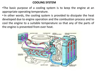
JCB T4F 444 Elec Engine (4 Cyl), T4F 448 Elec Engine (4 Cyl) Service Repair Manual Instant Download
Please open the website below to get the complete manualnn//

Download Presentation

Please find below an Image/Link to download the presentation.
The content on the website is provided AS IS for your information and personal use only. It may not be sold, licensed, or shared on other websites without obtaining consent from the author. Download presentation by click this link. If you encounter any issues during the download, it is possible that the publisher has removed the file from their server.
E N D
Presentation Transcript
Foreword The Operator's Manual You and others can be killed or seriously injured if you operate or maintain the machine without first studying the Operator's Manual. You must understand and follow the instructions in the Operator's Manual. If you do not understand anything, ask your employer or JCB dealer to explain it. SERVICE MANUAL Do not operate the machine without an Operator's Manual, or if there is anything on the machine you do not understand. Treat the Operator's Manual as part of the machine. Keep it clean and in good condition. Replace the Operator's Manual immediately if it is lost, damaged or becomes unreadable. ENGINE JCB T4F 444 Elec Engine (4 Cyl), JCB T4F 448 Elec Engine (4 Cyl) Contents 01 - Machine 06 - Body and Framework 09 - Operator Station 15 - Engine 18 - Fuel and Exhaust System 21 - Cooling System 33 - Electrical System 72 - Fasteners and Fixings 75 - Consumable Products 78 - After Sales EN - 9806/6400 - ISSUE 4 - 04/2018 This manual contains original instructions, verified by the manufacturer (or their authorized representative). Copyright 2017 JCB SERVICE All rights reserved. No part of this publication may be reproduced, stored in a retrieval system, or transmitted in any form or by any other means, electronic, mechanical, photocopying or otherwise, without prior permission from JCB SERVICE. www.jcb.com
15 - Engine 42 - Rocker and Fittings 00 - General 00 - General Introduction Introduction .................................................. 15-151 Technical Data ............................................. 15-152 Component Identification ............................. 15-153 Operation ..................................................... 15-154 Check (Condition) ........................................ 15-155 Remove and Install ..................................... 15-156 Disassemble and Assemble ........................ 15-158 The rocker assembly is an indirect valve actuating system consisting of rocker arms and a shaft. The rocker arm is an oscillating lever that conveys radial movement from the cam lobe into linear movement at the poppet valve to open it. One end is raised and lowered by a rotating lobe of the camshaft via a tappet and push rod while the other end acts on the bridge piece which is connected to the valve stem. 15 - 151 9806/6400-4 15 - 151
15 - Engine 42 - Rocker and Fittings 00 - General Technical Data Table 43. Rocker Levers, Rocker Shafts and Tappets Data Valve clearances measured at the valve end of the rockers (measured cold): - Inlet - Exhaust Valve clearances measured at the tappet end of the rockers (measured cold): - Inlet - Exhaust Rocker lever bore diameter - min - max Rocker shaft diameter - min - max Tappets stem diameter - min - max Tappet bore diameter - min - max Tappet height (maximum) 0.19 0.27 mm 0.56 0.64 mm 0.15 0.21 mm 0.43 0.49 mm 26.058 mm 26.092 mm 26.003 mm 26.021 mm 19.975 mm 19.985 mm 20 mm 20.021 mm 55.25 mm 15 - 152 9806/6400-4 15 - 152
https://www.ebooklibonline.com Hello dear friend! Thank you very much for reading. Enter the link into your browser. The full manual is available for immediate download. https://www.ebooklibonline.com
15 - Engine 42 - Rocker and Fittings 00 - General Component Identification Figure 92. 2 4 6 2 1 4 3 5 7 2 4 2 4 2 4 2 4 2 4 743830 1 Rocker shaft assembly 3 Rocker shaft - oil feed pedestal fixing bolt (x1) 5 Oil feed pedestal (x1) 7 Push rods (x8) 2 Rocker shaft fixing bolts (x7) 4 Pedestals (x7) 6 Bridge pieces (x8) 15 - 153 9806/6400-4 15 - 153
15 - Engine 42 - Rocker and Fittings 00 - General Operation rocker arm is permitted to return due to the camshafts rotation, the inside rises to allow the valve spring to close the valve. When the camshaft lobe raises the outside of the rocker arm, the inside presses down on the valve stem to open the valve. When the outside of the Figure 93. 1 Oil feed from main gallery 3 Shaft pedestal 5 Centre rocker shaft drilling 7 Rocker pivot bushes 9 Groove 2 Small transfer gallery 4 Rocker shaft fixing bolt hole 6 Cross drillings 8 Cross drilling Lubrication in each rocker transfers oil to the top of the rocker where it flows by gravity along a groove to the rocker tip. Oil is fed from the main gallery via a drilling which passes up through the crankcase and the cylinder head to a small transfer gallery under the rocker shaft pedestal. The oversize rocker shaft fixing bolt hole allows oil to pass into a drilling in the centre of the rocker shaft. Further cross drillings transfer oil to each of the rocker pivot bushes. A cross drilling 15 - 154 9806/6400-4 15 - 154
15 - Engine 42 - Rocker and Fittings 00 - General Check (Condition) 1. Check the rocker shaft and rocker bushings for signs of damage and excessive wear. Measure the rocker shaft diameter and rocker bearing bushes to confirm they are within service limits. Refer to Technical Data. Note: The rocker bearing bushes are not renewable. If a rocker bearing bush is damaged or worn the rocker must be renewed as a complete assembly. Refer to: PIL 15-42. 2. Make sure that all oil-ways and cross drillings in the rocker shaft, rocker arms and pedestals are clear and free from debris. Use an air line to blow through cross drillings. 15 - 155 9806/6400-4 15 - 155
15 - Engine 42 - Rocker and Fittings 00 - General Remove and Install 2. Get access to the engine. Before Removal 3. Disconnect and remove the fuel pipes from the fuel injectors, refer to Fuel pipes (PIL 18-96). 1. Make sure that the engine is safe to work on. If the engine has been running, let it cool before you start the service work. 4. Remove the rocker cover, refer to (PIL 15-42). Figure 94. 2 4 6 2 1 4 3 5 7 2 4 2 4 2 4 2 4 2 4 743830 1 Rocker shaft assembly 3 Rocker shaft - oil feed pedestal fixing bolt (x1) 5 Oil feed pedestal (x1) 7 Push rods (x8) 2 Rocker shaft fixing bolts (x7) 4 Pedestals (x7) 6 Bridge pieces (x8) 15 - 156 9806/6400-4 15 - 156
15 - Engine 42 - Rocker and Fittings 00 - General Remove 1. Remove the rocker shaft fixing bolts. DO NOT withdraw the bolts. Lift the rocker shaft assembly from the cylinder head complete with pedestals still attached. Important: Keep all pedestals and fixing bolts in their original positions. 2. Lift off the bridge pieces from the pairs of inlet and exhaust valves. 3. Withdraw the push rods from the cylinder block. Before Installation 1. Make sure that all items are clean and free from damage and corrosion. Refer to Check Condition (PIL 15-42). 2. Make sure that all oil-ways and cross drillings in the cylinder head, rocker shaft and pedestals are clear and free from debris. Use an air line to blow through the cross drillings. Install 1. The installation procedure is the opposite of the removal procedure. Additionally do the following steps. 2. Use a suitable degreasing agent to clean the top of the cylinder head. 3. Install the bridge pieces on to the pairs of inlet and exhaust valves in the cylinder head. 4. Insert the push rods into the cylinder block. Make sure that they engage with the camshaft tappets. 5. Install the rocker shaft assembly into the cylinder head. Make sure that the pedestals are located in their original positions. Note the position of the oil feed pedestal and the longer bolt. Make sure that the push rods engage with the tappet adjusters and that the rockers are located over the bridge pieces. 6. Tighten the bolts to the correct torque value. After Installation 1. Measure and adjust the valve clearances, refer to (PIL 15-30). Table 44. Torque Values Item 2 3 Nm 24 24 15 - 157 9806/6400-4 15 - 157
15 - Engine 42 - Rocker and Fittings 00 - General Disassemble and Assemble 2. Remove the rocker assembly. Refer to (PIL 15-42). Before Disassembly 1. Remove the rocker cover. Refer to (PIL 15-42). Figure 95. 2 2 2 3 1 2 2 4 4 4 5 4 5 6 8 7 4 1 Rocker shaft 3 Rocker shaft - Oil feed pedestal fixing bolt (x1) 5 Oil feed pedestal (x1) 7 Rockers - exhaust (x4) 2 Rocker shaft fixing bolts (x7) 4 Pedestals (x7) 6 Rockers - inlet (x4) 8 Wave washers (x8) 15 - 158 9806/6400-4 15 - 158
15 - Engine 42 - Rocker and Fittings 00 - General Disassemble 1. Lift out the rocker shaft fixing bolts, then slide the pedestals, rockers and wave washers off the rocker shaft as shown. Label the pedestals and rockers to make sure that they are installed in the correct positions on assembly. 2. Check the rocker shaft and rocker bushings for signs of damage and excessive wear. Refer to Check (Condition) (PIL 15-42). Assemble 1. The assembly procedure is the opposite of the disassemble procedure. Additionally do the following steps. 2. Lubricate the rocker shaft and rocker bearing bushes with clean engine oil. 3. Make sure that the rockers and pedestals are installed in their original positions along the rocker shaft. Note the position of the oil feed pedestal. 4. Insert the rocker shaft fixing bolts to hold the rockers and pedestals loosely in position before fitting the assembly into the cylinder head. Note the position of the longer bolt. After Assembly 1. Install the rocker assembly. Refer to (PIL 15-42). 2. Install the rocker cover. Refer to (PIL 15-42). 15 - 159 9806/6400-4 15 - 159
15 - Engine 42 - Rocker and Fittings 06 - Rocker Cover 06 - Rocker Cover Remove and Install 2. Clean the engine. Refer to Engine - Clean (PIL 15-00). Before Removal 1. Make sure that the engine is safe to work on. If the engine has been running, let it cool before you start the service work. Figure 96. D B A C A Rocker cover C Gasket B Bolts D Injector seals 15 - 160 9806/6400-4 15 - 160
15 - Engine 42 - Rocker and Fittings 06 - Rocker Cover Remove 1. Get access to the engine. 2. Remove the high pressure fuel pipes. Refer to Fuel Pipes (PIL 18-96). 3. Remove the fuel bleed off fuel pipes. Refer to Fuel Pipes (PIL 18-96). 4. Disconnect the electrical connectors at the fuel injectors. Refer to Fuel Injection (PIL 18-18). 5. Disconnect the electrical connector at the coolant temperature sensor. Refer to Engine Sensors (PIL 15-84). 6. Move the electrical harness away from the rocker cover. 7. Remove the bolts and lift the rocker cover from the cylinder head. 8. Discard the gasket. 9. The rocker cover injector seals must be replaced. Refer to Injector seals (PIL 18-18). Install 1. The installation procedure is the opposite of the removal procedure. Additionally do the following steps. 2. Remove all oil and sludge contamination from inside the rocker chamber. 3. Renew the injector seals. Refer to Injector seals (PIL 18-18). 4. Renew the rocker cover gasket. 5. Prevent damage to the seals. Put sleeves/covers on the four injectors. Apply a rubber lubricant to the seals and then install the rocker cover. 6. Tighten the bolts to the correct torque value. 7. Remove the sleeves/covers. After Installation 1. The high pressure fuel pipes must be replaced with new parts. Refer to Fuel Pipes (PIL 18-96). 2. Start the engine and check for oil and fuel leaks. Table 45. Torque Values Item B Nm 24 15 - 161 9806/6400-4 15 - 161
15 - Engine 42 - Rocker and Fittings 09 - Push Rod 09 - Push Rod Introduction Introduction .................................................. 15-162 Remove and Install ..................................... 15-163 Push rods are used in a reciprocating engine to open and close the valves. They are moved by the cams on the camshaft. One end is pushed up by the cam and the other end makes contact with the rocker arms which rotates and pushes the valve open. 15 - 162 9806/6400-4 15 - 162
15 - Engine 42 - Rocker and Fittings 09 - Push Rod Remove and Install Refer to: PIL 15-42-00. 15 - 163 9806/6400-4 15 - 163
15 - Engine 42 - Rocker and Fittings 21 - Tappet 21 - Tappet Figure 98. Remove and Install B Before Removal 1. Drain the oil from the engine. 2. Disconnect and remove the fuel pipes from the injectors. Refer to (PIL 18-96). C B Timing pin - crankshaft C Blanking plug 3. Remove the rocker cover. Refer to (PIL 15-42). 4. Remove the fuel injection pump. Refer to (PIL 18-18). 12. Remove the fuel injection pump drive gear. Refer to (PIL 15-51). 5. Remove the rocker assembly and push rods. Refer to (PIL 15-42). Removal 6. Remove the starter motor. Refer to (PIL 15-75). The engine must be inverted. DO NOT attempt to remove the camshaft and its drive gears with the engine upright. The tappets and push rods will fall into the engine and further dismantling will be required to retrieve them. 7. Remove the oil sump. Refer to (PIL 15-45). 8. Remove the flywheel. Refer to (PIL 15-54). 9. Remove the flywheel housing. Refer to (PIL 15-54). 1. Remove the camshaft timing pin. 2. Carefully withdraw the camshaft and gear assembly from the crankcase. Make sure you fully support the camshaft to prevent the lobes contacting the bearing surfaces in the crankcase. The bearing surfaces can easily be damaged by the sharp hard edges on the cam lobes. 10. Rotate the crankshaft until the camshaft timing pin can be inserted through the gear and into the aligning hole in the rear gear case. Figure 97. Figure 99. A A A Timing pin - camshaft 11. Remove the taper blanking plug and insert the crankshaft locking pin. The camshaft and crankshaft locking pins must be in position to lock the crankshaft and camshaft before removing the camshaft assembly. D A Timing pin - camshaft D Camshaft and drive gear 15 - 164 9806/6400-4 15 - 164
15 - Engine 42 - Rocker and Fittings 21 - Tappet Installation 3. Access the tappets through the apertures in the crankcase bedplate next to the crankshaft. Lift out the tappets from the crankcase using a suitable magnetic probe. Label the tappets to ensure replacement in their original positions. 1. Lubricate the tappets and tappet bores inside the crankcase with clean engine oil. 2. Insert the tappets in their original positions in the crankcase using a suitable magnetic probe. Figure 100. 3. Lubricate the camshaft bearing journals inside the crankcase with clean engine oil. F 4. Carefully insert the camshaft assembly into the crankcase as shown. Support the camshaft preventing the lobes contacting the bearing surfaces in the crankcase. Before meshing the camshaft gear with the crankshaft gear, rotate the camshaft until the timing hole in the gear aligns with the dowel hole in the gear casing. Insert the timing pin to lock the camshaft in this position. E E After Installation 1. Note that the fuel injection pump drive gear fixing nut is torque tightened as part of the fuel injection pump replacement procedure. Refer to (PIL 18-18). 2. Do the procedures in Before Removal in reverse order. E Tappet (8 off) F Magnetic probe Inspection 1. Inspect the camshaft gear teeth for signs of damage or excessive wear. 2. Inspect the cam lobes for signs of excessive wear, scoring or pitting. 3. Inspect the cam bearing surfaces for signs of excessive wear, or scoring. Check that the dimensions are within service limits. 4. Inspect the cam bearing surfaces inside the crankcase for signs of excessive wear, or scoring. Check that the dimensions are within service limits. 5. Inspect the bearing surfaces of the tappets for signs of excessive wear or damage. Check that the dimensions are within service limits. 6. Inspect the tappet bores inside the crankcase for signs of excessive wear or damage. Check that the dimensions are within service limits. 7. If any of the camshaft bearings or lobes are worn or damaged then the relative oil feed galleries in the crankcase and camshaft may be blocked. Make sure all oil ways are clear and free from debris. 15 - 165 9806/6400-4 15 - 165
15 - Engine 42 - Rocker and Fittings 24 - Tappet Cover 24 - Tappet Cover Install 1. The installation procedure is the opposite of the removal procedure. Additionally do the following steps. Remove and Install It is not necessary to remove the tappet covers unless a new rocker cover is to be installed. It is necessary to remove the tappet covers to measure and adjust the valve clearances. Refer to Valve- Adjust, Valve Clearances (PIL 15-30). 2. Inspect the tappet cover seals for signs of damage. Replace any damaged seals. 3. Install the tappet covers. Tighten the screws to the correct torque value. Table 46. Torque Values Remove Item A Nm 9 1. Make sure that the engine is safe to work on. If the engine has been running, let it cool before you start the service work. 2. Get access to the engine. 3. Clean the tappet covers and the adjacent areas of the rocker cover. Refer to Engine - Clean. Important: Make sure that the screws do not fall into the engine. 4. Remove the tappet cover screws. 5. Keep the screws away from the engine. 6. Use a screwdriver in the slot to remove the tappet covers. Make sure that dirt or debris does not fall into the engine. Figure 101. B B B B D B A E C A Screws B Tappet covers C Slot D Rocker cover E Tappet cover seals 15 - 166 9806/6400-4 15 - 166
15 - Engine 45 - Oil Sump 00 - General 00 - General Introduction Introduction .................................................. 15-169 Component Identification ............................. 15-170 Remove and Install ..................................... 15-171 The lubrication system distributes oil around the engine by a system of galleries and drillings in the crankcase and cylinder head. The oil lubricates and seals the moving parts of the engine, reducing friction and wear. In addition the oil plays an important role in cooling the engine by carrying heat from the engine to the cooler. A piston cooling jet sprays oil onto the underside of the pistons to keep them cool, refer to (PIL 15-36). Oil is drawn from the oil sump by the integral oil pump via the suction strainer. The strainer prevents any large particles of debris passing through, which may damage the pump. The oil passes from the outlet side of the pump through a relief valve which limits the maximum oil pressure by venting oil back to the inlet side of the pump, refer to (PIL 15-36). From the pump the oil passes through the oil cooler and filter, refer to (PIL 15-69 and PIL 15-21). After cooling and filtering, the oil passes into the main oil gallery. An oil pressure switch senses the oil pressure. From the main gallery oil is delivered, via drillings, to the crankshaft main bearings, rocker assembly, camshaft and timing gears. Note that drillings are through the crankcase and cylinder head. When the high pressure oil has passed through the bearings it reverts to sump pressure and splash lubricates the internal components such as rocker tips, cam lobes and timing gear teeth. Gravity drains the oil via drains into the cylinder head and crankcase, back into the oil sump. A drain slot allows the oil to drain from the timing case back to the oil sump. 15 - 169 9806/6400-4 15 - 169
15 - Engine 45 - Oil Sump 00 - General Component Identification Figure 102. 1 3 5 7 Oil sump Oil pump Filter Crankshaft main bearings - high pressure oil feed PTO (Power Take-Off) idler gear bearing/ timing case - high pressure oil feed Main high pressure oil feed gallery (crankcase) Green- Oil at sump pressure Pink- Oil at lower pressure but higher than sump pressure 2 4 6 8 Suction strainer Oil cooler Camshaft - high pressure oil feed Rocker assembly - high pressure oil feed 9 10 External high pressure oil feed connection (crankcase) - Turbocharger (if installed) Oil pressure switch 11 12 Red- Oil at high pressure 15 - 170 9806/6400-4 15 - 170
15 - Engine 45 - Oil Sump 00 - General Remove and Install Special Tools Description Template for Sealant Oil Sump - Pressed Oil Sump Location Dowel Template for Sealant Oil Sump (Cast) 2. Drain the engine oil. Part No. 892/01149 Qty. 1 Removal 1. Remove the fixing bolts and remove the oil sump from the engine. The oil sump may be difficult to remove due to adhesion of sealing compound. If necessary, carefully lever the mating flanges apart. Do not use excessive force, the oil sump could be damaged. Be sure to retrieve the oil pick up seal. 892/01150 2 892/12354 1 Consumables Description Clear Silicone Sealant Part No. 4102/0901 Size 0.31 L 2. Use a gasket removal compound, carefully remove all traces of sealing compound from the oil sump and engine mating faces. Do not allow the sealing compound to enter the engine. Before Removal 1. Make sure that the engine is safe to work on. If the engine has been running, make sure the engine has cooled sufficiently before you start. 3. Use a suitable degreasing agent to thoroughly clean the oil sump. Figure 103. 1 1b 3 Oil sump Integral baffle plates Oil pick up seal 1a 2 Integral suction tube Oil sump fixing bolts (x20) 15 - 171 9806/6400-4 15 - 171
Suggest: If the above button click is invalid. Please download this document first, and then click the above link to download the complete manual. Thank you so much for reading
15 - Engine 45 - Oil Sump 00 - General Installation Figure 105. X 1. Lightly smear the new oil pick up seal with oil and install into the bedplate as shown. Figure 104. X 3 Oil pick up seal 2. Install the two guide pins at the oil sump screw holes in the engine. Special Tool: Oil Sump Location Dowel (Qty.: 2) S T T2 Guide pins X 4mm Bead of sealant Hole Hole 3. Use the fixing bolts to locate the template to the oil sump mating face. Make sure that the template is the correct way round (note that holes are on different centres). Special Tool: Template for Sealant Oil Sump (Cast) (Qty.: 1) Special Tool: Template for Sealant Oil Sump - Pressed (Qty.: 1) 8. Position the oil sump with the suction tube outlet aligned with the oil pump inlet port on the engine. Take care not to damage the oil pick up seal when you install the oil sump. Damage to the seal could cause a drop in oil pressure and subsequently damage to the engine. 4. Apply a bead of sealing compound around the oil sump flange using the inside edge of the template as a guide as shown. Note the beads around holes. Length/Dimension/Distance: 4 mm Consumable: Clear Silicone Sealant 9. Locate the oil sump on the guide pins on the engine. Avoid smudging the sealant beads. DO NOT remove the guide pins until sufficient bolts have been installed to secure the oil sump. 10. Install the bolts and tighten the bolts to the correct torque value. Note that the bolts are not installed at 6 positions. 5. Carefully remove the template without smudging the sealant beads. Figure 106. 6. Apply a bead of sealant so as to join the sealant beads around holes with the bead around the oil sump flange. Length/Dimension/Distance: 4 mm 7. After applying the sealing compound, the oil sump must be installed and the bolts torque tightened within Duration: 5 min 2 Bolts Y No bolts to be installed at this position (x6) 15 - 172 9806/6400-4 15 - 172
https://www.ebooklibonline.com Hello dear friend! Thank you very much for reading. Enter the link into your browser. The full manual is available for immediate download. https://www.ebooklibonline.com