CASE IH AXIAL-FLOW® 6140 Tier 2 Combine Service Repair Manual Instant Download [YDG012001 - YEG012700] ,
Please open the website below to get the complete manualnn//

Download Presentation

Please find below an Image/Link to download the presentation.
The content on the website is provided AS IS for your information and personal use only. It may not be sold, licensed, or shared on other websites without obtaining consent from the author. Download presentation by click this link. If you encounter any issues during the download, it is possible that the publisher has removed the file from their server.
E N D
Presentation Transcript
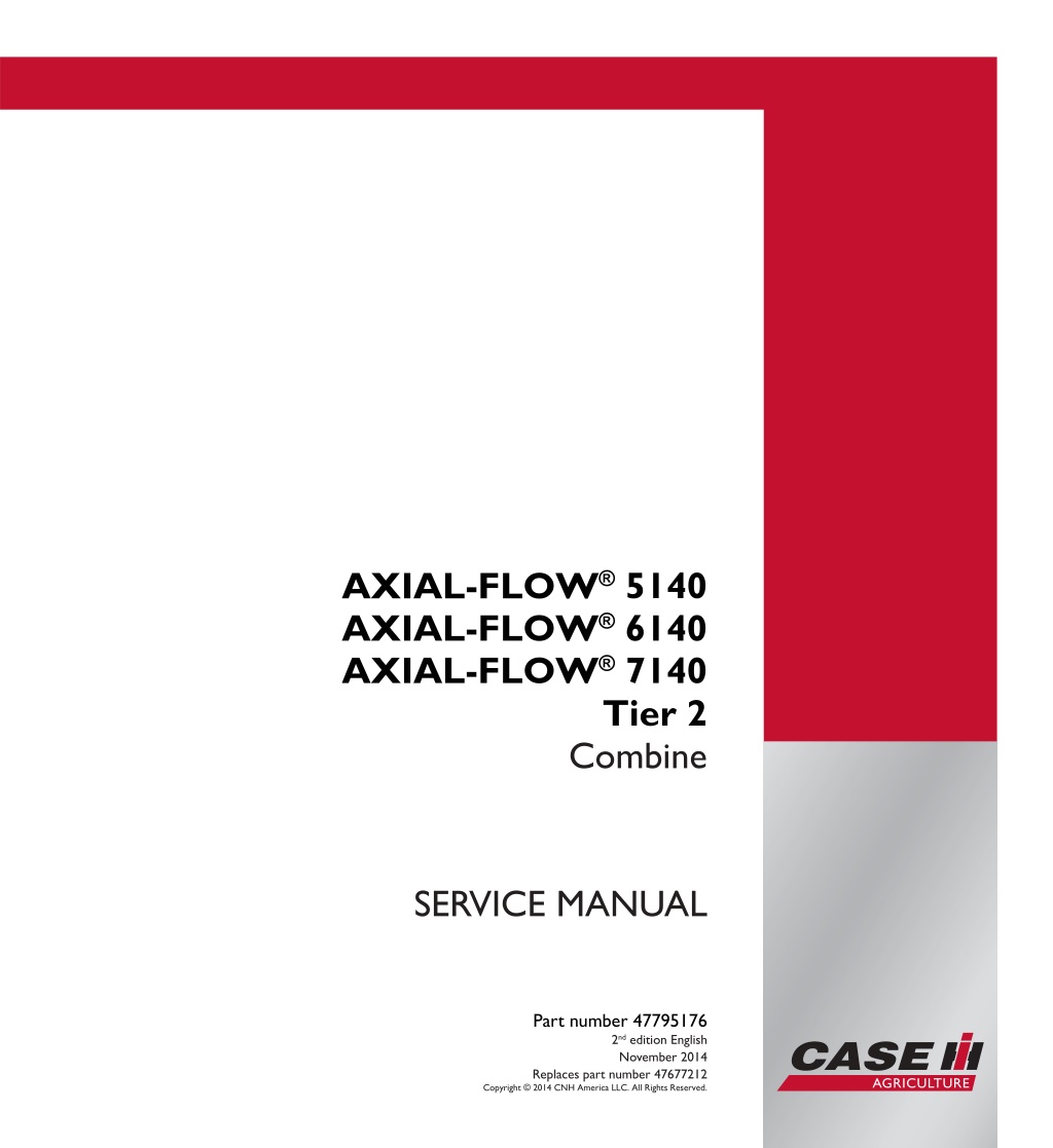
SERVICE MANUAL AXIAL-FLOW 5140 AXIAL-FLOW 6140 AXIAL-FLOW 7140 AXIAL-FLOW 5140 AXIAL-FLOW 6140 AXIAL-FLOW 7140 Tier 2 Combine Tier 2 Combine 1/4 SERVICE MANUAL Part number 47795176 Part number 47795176 2nd edition English November 2014 Replaces part number 47677212 Copyright 2014 CNH America LLC. All Rights Reserved.
SERVICE MANUAL AXIAL-FLOW 5140 [YDG012001 - YEG012700] , AXIAL-FLOW 5140 [YEG012701 - ] , AXIAL-FLOW 6140 [YDG012001 - YEG012700] , AXIAL-FLOW 6140 [YEG012701 - ] , AXIAL-FLOW 7140 [YDG012001 - YEG012700] , AXIAL-FLOW 7140 [YEG012701 - ] 47795176 17/11/2014 EN
Contents INTRODUCTION Engine....................................................................................... 10 [10.001] Engine and crankcase ............................................................. 10.1 [10.202] Air cleaners and lines .............................................................. 10.2 [10.216] Fuel tanks .......................................................................... 10.3 [10.254] Intake and exhaust manifolds and muffler ......................................... 10.4 [10.310] Aftercooler.......................................................................... 10.5 [10.400] Engine cooling system ............................................................. 10.6 [10.408] Oil cooler and lines................................................................. 10.7 [10.414] Fan and drive ...................................................................... 10.8 [10.419] Stationary air screen ............................................................... 10.9 Main gearbox and drive............................................................... 14 [14.100] Main gearbox and drive ............................................................ 14.1 Transmission.............................................................................. 21 [21.114] Mechanical transmission ........................................................... 21.1 [21.145] Gearbox internal components...................................................... 21.2 [21.182] Differential.......................................................................... 21.3 Front axle system ....................................................................... 25 [25.310] Final drives......................................................................... 25.1 Rear axle system........................................................................ 27 [27.100] Powered rear axle.................................................................. 27.1 [27.124] Final drive hub, steering knuckles, and shafts ..................................... 27.2 Hydrostatic drive......................................................................... 29 [29.100] Transmission and steering hydrostatic control..................................... 29.1 [29.134] Two-speed assembly............................................................... 29.2 [29.202] Hydrostatic transmission ........................................................... 29.3 47795176 17/11/2014
https://www.ebooklibonline.com Hello dear friend! Thank you very much for reading. Enter the link into your browser. The full manual is available for immediate download. https://www.ebooklibonline.com
[29.204] Reservoir, cooler, and lines ........................................................ 29.4 [29.218] Pump and motor components...................................................... 29.5 [29.300] Rear hydrostatic transmission...................................................... 29.6 Brakes and controls .................................................................... 33 [33.110] Parking brake or parking lock ...................................................... 33.1 [33.202] Hydraulic service brakes ........................................................... 33.2 Hydraulic systems....................................................................... 35 [35.000] Hydraulic systems.................................................................. 35.1 [35.102] Pump control valves................................................................ 35.2 [35.106] Variable displacement pump ....................................................... 35.3 [35.220] Auxiliary hydraulic pump and lines................................................. 35.4 [35.300] Reservoir, cooler, and filters........................................................ 35.5 [35.359] Main control valve.................................................................. 35.6 [35.410] Header or attachment height system .............................................. 35.7 [35.536] Crop processor system ............................................................ 35.8 Steering..................................................................................... 41 [41.101] Steering control .................................................................... 41.1 [41.106] Tie rods............................................................................. 41.2 [41.200] Hydraulic control components...................................................... 41.3 [41.206] Pump............................................................................... 41.4 Wheels...................................................................................... 44 [44.511] Front wheels........................................................................ 44.1 Cab climate control..................................................................... 50 [50.100] Heating............................................................................. 50.1 [50.104] Ventilation .......................................................................... 50.2 [50.200] Air conditioning..................................................................... 50.3 Electrical systems....................................................................... 55 [55.000] Electrical system ................................................................... 55.1 47795176 17/11/2014
[55.014] Engine intake and exhaust system................................................. 55.2 [55.100] Harnesses and connectors......................................................... 55.3 [55.201] Engine starting system............................................................. 55.4 [55.202] Cold start aid ....................................................................... 55.5 [55.301] Alternator........................................................................... 55.6 [55.302] Battery.............................................................................. 55.7 [55.408] Warning indicators, alarms, and instruments ...................................... 55.8 [55.421] Feeding control system ............................................................ 55.9 [55.512] Cab controls...................................................................... 55.10 [55.610] Ground speed control ............................................................ 55.11 [55.640] Electronic modules............................................................... 55.12 [55.785] Precision farming system ........................................................ 55.13 [55.988] Selective Catalytic Reduction (SCR) electrical system .......................... 55.14 [55.DTC] FAULT CODES.................................................................. 55.15 Attachments/Headers.................................................................. 58 [58.105] Attachment/Header reel control system............................................ 58.1 Product feeding.......................................................................... 60 [60.105] Floating roll, feed chain, and drive ................................................. 60.1 [60.110] Feeder housing..................................................................... 60.2 [60.150] Feeder drive system ............................................................... 60.3 [60.500] Gearbox housing................................................................... 60.4 Threshing .................................................................................. 66 [66.105] Concave............................................................................ 66.1 [66.110] Concave control system............................................................ 66.2 [66.260] Threshing mechanism drive system ............................................... 66.3 [66.331] Rotor ............................................................................... 66.4 Separation................................................................................. 72 [72.410] Rotary separator drive system ..................................................... 72.1 47795176 17/11/2014
[72.420] Rotary separator ................................................................... 72.2 Residue handling........................................................................ 73 [73.210] Straw chopper drive system........................................................ 73.1 [73.230] Straw chopper...................................................................... 73.2 [73.335] Chaff spreader ..................................................................... 73.3 Cleaning.................................................................................... 74 [74.000] Cleaning............................................................................ 74.1 [74.101] Cleaning drive systems ............................................................ 74.2 [74.114] Upper shaker shoe ................................................................. 74.3 [74.118] Lower shaker shoe ................................................................. 74.4 [74.130] Fan housing........................................................................ 74.5 [74.140] Tailings return system.............................................................. 74.6 Crop storage / Unloading............................................................. 80 [80.101] Clean grain elevator................................................................ 80.1 [80.150] Grain tank .......................................................................... 80.2 [80.175] Grain tank unload drive system .................................................... 80.3 [80.180] Grain tank unload .................................................................. 80.4 Platform, cab, bodywork, and decals............................................. 90 [90.100] Engine hood and panels ........................................................... 90.1 [90.105] Machine shields and guards ....................................................... 90.2 [90.124] Pneumatically-adjusted operator seat.............................................. 90.3 [90.150] Cab................................................................................. 90.4 [90.151] Cab interior......................................................................... 90.5 47795176 17/11/2014
INTRODUCTION 47795176 17/11/2014 1
INTRODUCTION Safety rules - Ecology and the environment AXIAL-FLOW 5140 AXIAL-FLOW 6140 AXIAL-FLOW 7140 ANZ --- APAC --- MEA ANZ --- APAC --- MEA ANZ --- APAC --- MEA Soil, air, and water quality is important for all industries and life in general. When legislation does not yet rule the treatment of some of the substances that advanced technology requires, sound judgment should govern the use and disposal of products of a chemical and petrochemical nature. Familiarize yourself with the relative legislation applicable to your country, and make sure that you understand this legislation. Where no legislation exists, obtain information from suppliers of oils, filters, batteries, fuels, anti-freeze, cleaning agents, etc., with regard to the effect of these substances on man and nature and how to safely store, use, and dispose of these substances. Helpful hints Avoid the use of cans or other inappropriate pressurized fuel delivery systems to fill tanks. Such delivery systems may cause considerable spillage. In general, avoid skin contact with all fuels, oils, acids, solvents, etc. Most of these products contain substances that may be harmful to your health. Modern oils contain additives. Do not burn contaminated fuels and or waste oils in ordinary heating systems. Avoid spillage when you drain fluids such as used engine coolant mixtures, engine oil, hydraulic fluid, brake fluid, etc. Do not mix drained brake fluids or fuels with lubricants. Store all drained fluids safely until you can dispose of the fluids in a proper way that complies with all local legislation and available resources. Do not allow coolant mixtures to get into the soil. Collect and dispose of coolant mixtures properly. The air-conditioning system contains gases that should not be released into the atmosphere. Consult an air-condi- tioning specialist or use a special extractor to recharge the system properly. Repair any leaks or defects in the engine cooling system or hydraulic system immediately. Do not increase the pressure in a pressurized circuit as this may lead to a component failure. Protect hoses during welding. Penetrating weld splatter may burn a hole or weaken hoses, allowing the loss of oils, coolant, etc. Battery recycling Batteries and electric accumulators contain several substances that can have a harmful effect on the environment if the batteries are not properly recycled after use. Improper disposal of batteries can contaminate the soil, groundwater, and waterways. CASE IH strongly recommends that you return all used batteries to a CASE IH dealer, who will dispose of the used batteries or recycle the used batteries properly. In some countries, this is a legal requirement. Mandatory battery recycling NOTE: The following requirements are mandatory in Brazil. Batteries are made of lead plates and a sulfuric acid solution. Because batteries contain heavy metals such as lead, CONAMA Resolution 401/2008 requires you to return all used batteries to the battery dealer when you replace any batteries. Do not dispose of batteries in your household garbage. Points of sale are obliged to: Accept the return of your used batteries Store the returned batteries in a suitable location Send the returned batteries to the battery manufacturer for recycling 47795176 17/11/2014 4
INTRODUCTION Safety rules - Personal safety AXIAL-FLOW 5140 AXIAL-FLOW 6140 AXIAL-FLOW 7140 ANZ --- APAC --- MEA ANZ --- APAC --- MEA ANZ --- APAC --- MEA Carefully study these precautions, and those included in the external attachment operators manual, and insist that they be followed by those working with and for you. 1. Thoroughly read and understand this manual and the attachment Operator s Manual before operating this or any other equipment. 2. Be sure all people and pets are clear of the machine before starting. Sound the horn, if equipped, three times before starting engine. 3. Only the operator should be on the machine when in operation. Never allow anyone to climb on to the machine while it is in motion. If the machine is equipped with an Instructors Seat, this must only be used for training purposes. Passengers must not be allowed to use the Instructors Seat. 4. Keep all shields in place. Never work around the machine or any of the attachments while wearing loose clothing that might catch on moving parts. 5. Observe the following precautions whenever lubricating the machine or making adjustments. Disengage all clutching levers or switches. Lower the attachment, if equipped, to the ground or raise the attachment completely and engage the cylinder safety locks. Completing these actions will prevent the attachment from lowering unexpectedly. Engage the parking brake. Shut off the engine and remove the key. Wait for all machine movement to stop before leaving the operators platform. 6. Always keep the machine in gear while travelling downhill. 7. The machine should always be equipped with sufficient front or rear axle weight for safe operation. 8. Under some field conditions, more weight may be required at the front or rear axle for adequate stability. This is especially important when operating in hilly conditions or/when using heavy attachments. 9. Always lower the attachment, shut off the engine, set the parking brake, engage the transmission gears, remove the key and wait for all machine movement to stop before leaving the operators platform. 10. If the attachment or machine should become obstructed or plugged; set the parking brake, shut off the engine and remove the key, engage the transmission gears, wait for all machine or attachment motion to come to a stop, before leaving the operators platform to removing the obstruction or plug. 11. Never disconnect or make any adjustments to the hydraulic system unless the machine and/or the attachment is lowered to the ground or the safety lock(s) is in the engaged position. 12. Use of the flashing lights is highly recommended when operating on a public road. 13. When transporting on a road or highway, use accessory lights and devices for adequate warning to the opera- tors of other vehicles. In this regard, check local government regulations. Various safety lights and devices are available from your CASE IH dealer. 14. Practice safety 365 days a year. 15. Keep all your equipment in safe operating condition. 16. Keep all guards and safety devices in place. 17. Always set the parking brake, shut off the engine and remove the key, engage the transmission gears, wait for all machine or attachment motion to come to a stop, before leaving the operators platform to service the machine and attachment. 18. Remember: A careful operator is the best insurance against an accident. 19. Extreme care should be taken in keeping hands and clothing away from moving parts. 47795176 17/11/2014 5
SERVICE MANUAL Engine AXIAL-FLOW 5140 [YDG012001 - YEG012700] , AXIAL-FLOW 5140 [YEG012701 - ] , AXIAL-FLOW 6140 [YDG012001 - YEG012700] , AXIAL-FLOW 6140 [YEG012701 - ] , AXIAL-FLOW 7140 [YDG012001 - YEG012700] , AXIAL-FLOW 7140 [YEG012701 - ] 47795176 17/11/2014 10
Engine - Engine and crankcase Engine - Install AXIAL-FLOW 5140 ANZ --- APAC --- MEA 1. Attach suitable lifting chains (1) to the engine lift brack- ets (2) and attach to a suitable lifting device. Lift engine into position at the gearbox. 1 NH12AF001337A 2. Guide engine into the PTO gearbox and install twelve gearbox to engine mount bolts. 2 NH12AF001336A 47795176 17/11/2014 10.1 [10.001] / 3
Engine - Engine and crankcase 3. Install flange bolts (1) to the engine mounts (2). Hand tighten at this time. 3 NHIL14AF00229AA 4 NHIL14AF00230AA 5 NHIL14AF00231AA 6 NHIL14AF00232AA 47795176 17/11/2014 10.1 [10.001] / 4
Engine - Engine and crankcase 4. Connect the fuel supply line (1). 7 NH12AF001323A 8 NH12AF001322A 5. Connect the fuel return line (1). 9 NHIL14AF00228AA 47795176 17/11/2014 10.1 [10.001] / 5
Engine - Engine and crankcase 6. Connect the engine pre-heater connector (1) to the en- gine pre-heater (2) . 10 NH12AF001319A 11 NH12AF001320A 7. Connect the electrical connections (1) and (2) to the Engine Control Unit (ECU) (3). 12 NHIL14AF00227AA 8. Install cable ties to retain the harness to the engine. 47795176 17/11/2014 10.1 [10.001] / 6
Engine - Engine and crankcase Next Operations Engine starter - Install (55.201) Alternator - Install (55.301) Diesel Oxidation Catalyst (DOC) - Install (10.500) Exhaust pipes - Install exhaust tube from turbo charger to Diesel Oxidation Catalyst (DOC) (10.254) Selective Catalytic Reduction (SCR) muffler and catalyst - Install (10.500) Exhaust pipes - Install mixer tube (10.254) Fan and drive - Install (10.414) Aftercooler air supply and return lines - Install return air tube from cooler to intake manifold (10.310) Aftercooler air supply and return lines - Install air supply tube from turbocharger to lower cooler box (10.310) Selective Catalytic Reduction (SCR) muffler and catalyst - Install (10.500) Air intake system - Install (10.202) Radiator coolant tubes - Install (10.400) Deaeration tank - Install (10.400) Engine - Install engine oil drain line and drain valve (10.001) Engine hood and panels - Install (90.100) Engine cooling system - Filling (10.400) Engine - Filling engine oil (10.001) Battery - Install (55.302) 9. Disconnect the fuel pump wire connector (1) to disable the fuel pump (2). 10. Check the engine oil level and top off if necessary. 11. Crank the engine over for three ten second intervals. This will distribute lubricating oil to the engine oper- ating systems and will allow oil pressure to be built before starting the engine. 13 NHIL14AF00437AA 12. Connect the fuel pump wire connector (1) to the fuel pump (2) and bleed the air from fuel injection system, as described in the Operators manual. 13. Start the engine and check all hoses, fittings and clamps for leaks. NOTICE: Monitor the instrument warning light bar at all times during initial engine start up to ensure the engine has proper oil pressure. Shut down the engine immediately if oil pressure is not adequate. 14. Ensureallelectricalcomponentsareworkingproperly. 14 NHIL14AF00437AA 47795176 17/11/2014 10.1 [10.001] / 7
Engine - Engine and crankcase Engine - Remove AXIAL-FLOW 6140 AXIAL-FLOW 7140 ANZ --- APAC --- MEA ANZ --- APAC --- MEA CAUTION Unexpected machine movement! 1. Disengage all drives. 2. Engage parking brake. 3. Lower all attachments to the ground, or raise and engage all safety locks. 4. Shut off engine. 5. Remove key from key switch. 6. Switch off battery key, if installed. 7. Wait for all machine movement to stop. Failure to comply could result in minor or moderate injury. C0038A Prior operation: Battery - Remove (55.302) Prior operation: Engine hood and panels - Remove (90.100) Prior operation: Engine - Drain fluid (10.001) Prior operation: Engine - Remove engine oil drain line and drain valve (10.001) Prior operation: Engine cooling system - Drain fluid (10.400). Prior operation: Deaeration tank - Remove (10.400) . Prior operation: Radiator coolant tubes - Remove (10.400) Prior operation: Air intake system - Remove (10.202) Prior operation: Aftercooler air supply and return lines - Remove air supply tube from turbocharger to upper cooler box (10.310) Prior operation: Aftercooler air supply and return lines - Remove return air tube from cooler to intake manifold (10.310) Prior operation: Fan and drive - Remove (10.414) Prior operation: Exhaust pipes - Remove mixer tube (10.254) Prior operation: Exhaust pipes - Remove exhaust tube from turbo charger to Diesel Oxidation Catalyst (DOC) (10.254) Prior operation: Selective Catalytic Reduction (SCR) muffler and catalyst - Remove (10.500) Prior operation: Diesel Oxidation Catalyst (DOC) - Remove (10.500) Prior operation: Air-conditioning compressor lines - Remove (50.200) Prior operation: Engine starter - Remove (55.201) Prior operation: Alternator - Remove (55.301) 47795176 17/11/2014 10.1 [10.001] / 8
Engine - Engine and crankcase 1. Park machine on level surface and chock front and rear tires. 1 NH12AF001411A 2. Swing the unload tube outward to gain engine removal access. 2 NHIL14AF00226AA NOTE: Retain all hardware for installation of the engine. 3. Disconnect the electrical connections (1) and (2) at the Engine Control Unit (ECU) (3). 3 NHIL14AF00397AA 47795176 17/11/2014 10.1 [10.001] / 9
Engine - Engine and crankcase 4. Disconnect the grid heater connector (1) to the engine grid heater relay (2) . 5. Disconnect remaining electrical connections from wire harness to engine. Remove all wire straps retaining the harness to the engine. 4 NHIL14AF00396AA 6. Disconnect the fuel supply line (1). 5 NHIL14AF00391AA 7. Disconnect the fuel return line (1). 6 NHIL14AF00390AA 47795176 17/11/2014 10.1 [10.001] / 10
Engine - Engine and crankcase 8. Return the unload tube (1) to the transport position and use it to support the main PTO gearbox (2). The main PTO gearbox must be supported during the engine re- moval. 7 NH12AF001335A 8 NH12AF001333A 9. Remove the twelve bolts (1) retaining the main PTO gearbox to the engine. 9 NH12AF001336A 10. Attachsuitableliftingchains(1)totheengineliftbrack- ets (2) and attach to a suitable lifting device. Support the engine while removing the engine mounts. 10 NH12AF001337A 47795176 17/11/2014 10.1 [10.001] / 11
Engine - Engine and crankcase 11. Remove the flange bolts (1) from the engine mounts (2). 11 NHIL14AF00392AA 12 NHIL14AF00393AA 47795176 17/11/2014 10.1 [10.001] / 12
Engine - Engine and crankcase 13 NHIL14AF00394AA 14 NHIL14AF00395AA 12. Slowly lift the engine (1) away from the main PTO gearbox (2) and remove the engine from the machine. 15 NH12AF001337A 47795176 17/11/2014 10.1 [10.001] / 13
Engine - Engine and crankcase Engine - Install AXIAL-FLOW 6140 AXIAL-FLOW 7140 ANZ --- APAC --- MEA ANZ --- APAC --- MEA 1. Attach suitable lifting chains (1) to the engine lift brack- ets (2) and attach to a suitable lifting device. Lift engine into position at the gearbox. 1 NH12AF001337A 2. Guide engine into the PTO gearbox and install twelve gearbox to engine mount bolts. 2 NH12AF001336A 47795176 17/11/2014 10.1 [10.001] / 14
Suggest: If the above button click is invalid. Please download this document first, and then click the above link to download the complete manual. Thank you so much for reading
Engine - Engine and crankcase 3. Install flange bolts (1) to the engine mounts (2). Hand tighten at this time. 3 NHIL14AF00392AA 4 NHIL14AF00393AA 47795176 17/11/2014 10.1 [10.001] / 15
https://www.ebooklibonline.com Hello dear friend! Thank you very much for reading. Enter the link into your browser. The full manual is available for immediate download. https://www.ebooklibonline.com