Caterpillar Cat D6H and D6H LGP SERIES II TRACK-TYPE TRACTOR (Prefix 2KD) Service Repair Manual Instant Download (2KD05500 and up)
Please open the website below to get the complete manualnn// n

Download Presentation

Please find below an Image/Link to download the presentation.
The content on the website is provided AS IS for your information and personal use only. It may not be sold, licensed, or shared on other websites without obtaining consent from the author. Download presentation by click this link. If you encounter any issues during the download, it is possible that the publisher has removed the file from their server.
E N D
Presentation Transcript
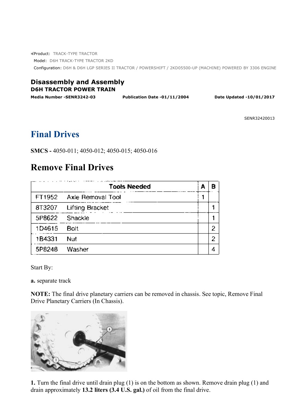
w 1/12(W) Product: TRACK-TYPE TRACTOR Model: D6H TRACK-TYPE TRACTOR 2KD Configuration: D6H & D6H LGP SERIES II TRACTOR / POWERSHIFT / 2KD05500-UP (MACHINE) POWERED BY 3306 ENGINE Disassembly and Assembly D6H TRACTOR POWER TRAIN Media Number -SENR3242-03 Publication Date -01/11/2004 Date Updated -10/01/2017 SENR32420013 Final Drives SMCS - 4050-011; 4050-012; 4050-015; 4050-016 Remove Final Drives Start By: a. separate track NOTE: The final drive planetary carriers can be removed in chassis. See topic, Remove Final Drive Planetary Carriers (In Chassis). 1. Turn the final drive until drain plug (1) is on the bottom as shown. Remove drain plug (1) and drain approximately 13.2 liters (3.4 U.S. gal.) of oil from the final drive. https://127.0.0.1/sisweb/sisweb/techdoc/techdoc_print_page.jsp?returnurl=/sisweb/siswe... 2022/2/2
w 2/12(W) 2. Remove the cover from the final drive and remove the O-ring seal from the cover. 3. Install tooling (A) and remove the outer axle. 4. Adjust the top bracket on tooling (B) so that dimension (X) is 213 mm (8.4 in). The lower mounting bracket must be installed with the spacers outward as shown. 5. Remove two of the bolts from the sprocket segments. Fasten a hoist and install tooling (B) onto the final drive. NOTICE https://127.0.0.1/sisweb/sisweb/techdoc/techdoc_print_page.jsp?returnurl=/sisweb/siswe... 2022/2/2
w 3/12(W) Bolts (4) hold the steering clutch and brake to the main case and frame. Do not remove bolts (4). 6. Remove bolts (2) that hold the final drive to the main case and frame. 7. The weight of the final drive is 490 kg (1075 lb). Remove four bolts (3) that hold the final drive and steering clutch and brake together. 8. Use tooling (B) and remove the final drive from the machine. 9. Remove the O-ring seal from either the face of the steering clutch or the final drive hub. Install Final Drives 1. Inspect the condition of O-ring seals and replace if necessary. 2. Put the O-ring seal in position on the face of the steering clutch. https://127.0.0.1/sisweb/sisweb/techdoc/techdoc_print_page.jsp?returnurl=/sisweb/siswe... 2022/2/2
https://www.ebooklibonline.com Hello dear friend! Thank you very much for reading. Enter the link into your browser. The full manual is available for immediate download. https://www.ebooklibonline.com
w 4/12(W) 3. Fasten a hoist and install tooling (B) onto the final drive. Adjust tooling (B) if necessary to put the final drive in a level position. 4. Put the final drive in position onto the frame and install four bolts (3) that hold the final drive to the steering clutch and brake. 5. Install bolts (2) that hold the final drive and steering clutch and brake to the main case and frame. Remove tooling (B). 6. Put SAE 30 oil on the threads of the segment bolts. Install the bolts and nuts with the nuts and washers against the final drive. Tighten the nuts to a torque of 175 40 N m (130 30 lb ft). Tighten the nuts 1/3 of a turn more. 7. Install tool (A) onto the outer axle and install the axle into the final drive. 8. Install the O-ring seal onto the cover and install the cover onto the final drive. 9. Rotate the final drive so drain plug (1) is toward the bottom. Fill the final drive with oil to the bottom of the fill plug hole. See the Operation And Maintenance Guide for the type of oil and capacity. End By: a. connect track Disassemble Final Drives https://127.0.0.1/sisweb/sisweb/techdoc/techdoc_print_page.jsp?returnurl=/sisweb/siswe... 2022/2/2
w 5/12(W) Start By: a. remove final drives 1. Install tooling (A) onto the planetary carrier and attach a hoist. 2. The weight of the planetary carrier is 137 kg (301 lb). Remove bolts (1) that hold the planetary carrier to the hub. Remove planetary carrier (3) and the two O-ring seals from the hub. 3. Remove three retainers (2). https://127.0.0.1/sisweb/sisweb/techdoc/techdoc_print_page.jsp?returnurl=/sisweb/siswe... 2022/2/2
w 6/12(W) 4. Support planetary carrier (3), from underneath, to prevent damage. Use tooling (B) and a press and remove the three planetary gear shafts. 5. Remove three planetary gears (4) from carrier (3). 6. Remove bearing cones (5) from each of the gears (4). 7. Remove the bearing cups from each side of the gears. 8. Remove ten bolts (6) and retainer (7). 9. The weight of the hub and ring gear (8) is 68 kg (150 lb). Use nylon straps and a hoist and remove the hub and ring gear (8). https://127.0.0.1/sisweb/sisweb/techdoc/techdoc_print_page.jsp?returnurl=/sisweb/siswe... 2022/2/2
w 7/12(W) 10. Turn hub (9) and ring gear (8) over. Remove retaining ring (10). The weight of hub (9) is 37 kg (82 lb). The weight of ring gear (8) is 32 kg (71 lb). Use nylon straps and a hoist and remove hub (9). 11. Install tooling (C) onto hub (12). NOTICE Do not lift hub (12) high enough to make contact with the fitting on the hydraulic cylinder, [part of tooling (C)]. 12. Use tooling (C) and loose hub (12) from spindle (13). Remove tooling (C). 13. Remove bearing cone (11). https://127.0.0.1/sisweb/sisweb/techdoc/techdoc_print_page.jsp?returnurl=/sisweb/siswe... 2022/2/2
w 8/12(W) 14. The weight of hub (12) is 180 kg (395 lb). Install tooling (D) and attach a hoist. Remove hub (12) from spindle (13). 15. Turn hub (12) over and remove Duo-Cone Seal (15). Use a hammer and a punch and remove bearing cup (16). 16. Turn the hub over and remove bearing cup (14) from the hub. NOTE: If the Duo-Cone Seals are to be used again, put identification marks on the seals so they can be assembled and installed in their original position. NOTICE Bearing cone (18) may be damaged if it is removed from spindle (13). https://127.0.0.1/sisweb/sisweb/techdoc/techdoc_print_page.jsp?returnurl=/sisweb/siswe... 2022/2/2
w 9/12(W) 17. Remove Duo-Cone Seal (19) from spindle (13). 18. If necessary, remove bearing cone (18) from the spindle. 19. Remove lip-type seal (17) from spindle (13). Assemble Final Drives 1. Put clean oil on all of the parts during assembly. 2. Use tooling (B) and install lip-type seal (17) into spindle (13). Put clean oil on the lip of the seal. 3. Heat bearing cone (18) to a maximum temperature of 135 C (275 F). Install bearing cone (18) onto spindle (13). NOTE: Before installing any of the Duo-Cone Seals, see Installation Of the Duo-Cone Floating Seals in this module. 4. Use tool (E) and install the Duo-Cone Seal onto spindle (13). https://127.0.0.1/sisweb/sisweb/techdoc/techdoc_print_page.jsp?returnurl=/sisweb/siswe... 2022/2/2
w 10/12(W) 5. Lower the temperature of bearing cups (14) and (16) and install them into hub (12). 6. Use tool (E) and install the Duo-Cone Seal into hub (12). 7. Install tooling (D) onto hub (12) and attach a hoist. Carefully, put hub (12) in position on spindle (13). 8. Heat bearing cone (11) to a maximum temperature of 135 C (275 F). Install bearing cone (11) onto spindle (13). 9. Use nylon straps and a hoist and put hub (9) in position in gear (8) and install retaining ring (10). https://127.0.0.1/sisweb/sisweb/techdoc/techdoc_print_page.jsp?returnurl=/sisweb/siswe... 2022/2/2
w 11/12(W) 10. Turn the hub and gear (8) over and install nylon straps. Attach a hoist to the nylon straps and put the hub and the gear in position in hub (12). 11. Put retainer (7) in position and install ten bolts (6), while slowly rotating the hub. Tighten bolts (6) evenly to a torque of 135 15 N m (100 11 lb ft). The retainer must be in contact with the end of spindle (13) after bolts (6) have been tightened. 12. Lower the temperature of bearing cups (20) and (21) and install them into three planetary gears (4). https://127.0.0.1/sisweb/sisweb/techdoc/techdoc_print_page.jsp?returnurl=/sisweb/siswe... 2022/2/2
w 12/12(W) 13. Put the planetary carrier in position in a press. Planetary shaft retainer (2) should be in position and supported so as to act as a positive stop for the shaft when it is installed. NOTICE Shaft (22) must be installed correctly or bearing preload will be incorrect and damage will result. 14. Put planetary gear (4) in position in the planetary carrier. 15. Lower the temperature of shaft (22) and use a press to install it into the planetary carrier. The end of shaft (22) must be installed flush with the retainer surface of the planetary carrier for correct bearing preload. Make sure the gear will rotate by hand after it has been installed. If it will not rotate by hand, the problem should be found and corrected. Repeat the procedure for three shafts. 16. Install three retainers (2) on shafts (22). 17. Install tooling (A) and attach a hoist. Install the two O-ring seals onto the planetary carrier. Align the drain hole in the carrier with the drain hole in the hub. 18. Put the planetary carrier in position on the hub. 19. Install the bolts that hold the planetary carrier to the hub. Remove tooling (A). https://127.0.0.1/sisweb/sisweb/techdoc/techdoc_print_page.jsp?returnurl=/sisweb/siswe... 2022/2/2
w 1/7(W) Product: TRACK-TYPE TRACTOR Model: D6H TRACK-TYPE TRACTOR 2KD Configuration: D6H & D6H LGP SERIES II TRACTOR / POWERSHIFT / 2KD05500-UP (MACHINE) POWERED BY 3306 ENGINE Disassembly and Assembly D6H TRACTOR POWER TRAIN Media Number -SENR3242-03 Publication Date -01/11/2004 Date Updated -10/01/2017 SENR32420014 Final Drive, Steering Clutch And Brake SMCS - 4050; 4100-011; 4100-012; 4100-029 Remove Final Drive, Steering Clutch And Brake Start By: a. separate track 1. Turn the final drive until drain plug (1) is on the bottom as shown. Remove drain plug (1) and drain approximately 11.4 liters (3 U.S. gal.) of oil from the final drive. 2. Remove the three bolts and the cover from the final drive. Remove the O-ring seal from the cover. https://127.0.0.1/sisweb/sisweb/techdoc/techdoc_print_page.jsp?returnurl=/sisweb/siswe... 2022/2/2
w 2/7(W) 3. Use tool (A) and remove the outer axle shaft. 4. Use tool (A) and remove the inner axle shaft. 5. Adjust the lifting shackle on the 8T3207 Lift Bracket [part of tooling (B)] so distance (X) is 63.5 mm (2.5 in). The lower mounting bracket should be installed so spacers (2) will be against the sprocket. 6. Remove two bolts from the sprocket segments. Fasten a hoist and install tooling (B) on the final drive as shown. https://127.0.0.1/sisweb/sisweb/techdoc/techdoc_print_page.jsp?returnurl=/sisweb/siswe... 2022/2/2
w 3/7(W) 7. Remove 26 bolts (3) that hold the final drive and steering clutch and brake to the frame. NOTICE Do not remove four bolts (4) that hold the final drive to the steering clutch and brake. 8. The weight of the final drive and steering clutch and brake assembly is 682 kg (1500 lb). Remove two bolts (5) that hold the steering clutch and brake to the frame. 9. Use tooling (B) and a hoist and remove the final drive and steering clutch and brake as a unit. Install Final Drive, Steering Clutch And Brake https://127.0.0.1/sisweb/sisweb/techdoc/techdoc_print_page.jsp?returnurl=/sisweb/siswe... 2022/2/2
w 4/7(W) 1. Inspect all O-ring seals for damage and replace if necessary. 2. Fasten a hoist and install tooling (B) onto the final drive. Make an adjustment to tooling (B) if needed, to level the final drive and steering clutch and brake. 3. Put the final drive, steering clutch and brake in position on the tractor. 4. Install two bolts (5) that hold the steering clutch and brake. 5. Install 26 bolts (3) that hold the final drive, steering clutch and brake in position. Remove tooling (B). https://127.0.0.1/sisweb/sisweb/techdoc/techdoc_print_page.jsp?returnurl=/sisweb/siswe... 2022/2/2
w 5/7(W) 6. Put SAE 30 oil on the threads of two segment bolts. Install so the head of the bolts are against the segment and so the washers and nuts are against the final drive. 7. Tighten the nuts to a torque of 175 40 N m (130 30 lb ft). Tighten the nuts 1/3 of a turn more. 8. Use tool (A) and install the inner axle. Remove tool (A). 9. Use tool (A) and install the outer axle. Remove tool (A). 10. Put the O-ring seal in position on the cover and install the cover on the final drive. 11. Rotate the final drive so drain plug (1) is toward the bottom. Fill the final drive with oil to the bottom of the fill plug hole. See the Operation and Maintenance Guide for the correct type of oil and capacity. End By: a. connect track Seperate And Connect Final Drive, Steering Clutch And Brake Start By: a. remove final drive, steering clutch and brake https://127.0.0.1/sisweb/sisweb/techdoc/techdoc_print_page.jsp?returnurl=/sisweb/siswe... 2022/2/2
w 6/7(W) 1. Remove O-ring seal (1). 2. The weight of the steering clutch and brake assembly is 255 kg (560 lb). Install tooling (A) and attach a hoist as shown. 3. Remove bolts (2). 4. Remove the steering clutch and brake from the final drive. 5. Turn the steering clutch and brake over and remove O-ring seal (3). NOTE: The following Steps are for connection of the final drive and steering clutch and brake. 6. Inspect the O-ring seals for damage and replace if necessary. Put clean oil on the O-ring seals. 7. Put O-ring seal (3) in position on the steering clutch and brake. 8. Install tooling (A) and attach a hoist. Put the steering clutch and brake in position on the final drive. 9. Install bolts (2) that hold the steering clutch and brake to the final drive. 10. Put O-ring seal (1) in position on the steering clutch and brake. End By: a. install final drive, steering clutch and brake. Wed Feb 2 08:27:09 UTC+0800 2022 https://127.0.0.1/sisweb/sisweb/techdoc/techdoc_print_page.jsp?returnurl=/sisweb/siswe... 2022/2/2
Our support email: ebooklibonline@outlook.com
https://www.ebooklibonline.com Hello dear friend! Thank you very much for reading. Enter the link into your browser. The full manual is available for immediate download. https://www.ebooklibonline.com