Understanding Positive Displacement Compressors in Fluid Machinery
Study the theoretical principles and operation of positive displacement compressors, focusing on reciprocating compressors in the Chemical Process Industry. Learn about indicator diagrams and the unique characteristics of reciprocating compressors. Explore the main components in compressed air systems, capacity regulations, and types of compressors. Discover the inefficiencies in compressors and the significant losses in compressed air systems.
- Positive Displacement Compressors
- Reciprocating Compressors
- Indicator Diagrams
- Compressed Air Systems
- Fluid Machinery

Uploaded on Jul 25, 2024 | 0 Views
Download Presentation

Please find below an Image/Link to download the presentation.
The content on the website is provided AS IS for your information and personal use only. It may not be sold, licensed, or shared on other websites without obtaining consent from the author. Download presentation by click this link. If you encounter any issues during the download, it is possible that the publisher has removed the file from their server.
E N D
Presentation Transcript
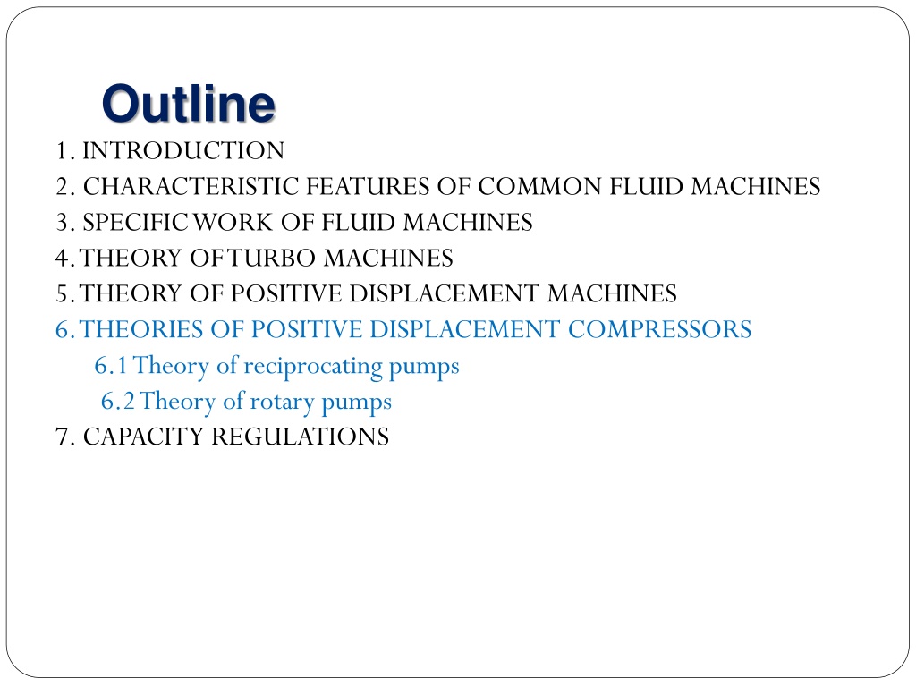
Outline 1. INTRODUCTION 2. CHARACTERISTIC FEATURES OF COMMON FLUID MACHINES 3. SPECIFIC WORK OF FLUID MACHINES 4. THEORY OF TURBO MACHINES 5. THEORY OF POSITIVE DISPLACEMENT MACHINES 6. THEORIES OF POSITIVE DISPLACEMENT COMPRESSORS 6.1 Theory of reciprocating pumps 6.2 Theory of rotary pumps 7. CAPACITY REGULATIONS
Introduction Significant Inefficiencies Compressors: 5 to > 50,000 hp 70 90% of compressed air is lost
Main Components in Compressed Air Systems Intake air filters Inter-stage coolers After coolers Air dryers Moisture drain traps Receivers
Types of Compressors Two Basic Compressor Types Type of compressor Positive displacement Dynamic Rotary Centrifugal Axial Reciprocating
6.1 Theory of Positive Displacement Compressors In this chapter we study the theoretical principles behind the design and operation of positive displacement compressors. There are many similarities between the theories of rotary and reciprocating compressors. reciprocating compressors are the most dominating one, hence more emphasis is given to reciprocating compressors. Type of compressor Positive displacement Dynamic Rotary Centrifugal Axial Reciprocating
Reciprocating Compressors are the most common positive displacement compressors used in the CPI. are special preferred for small capacity and high compression ratio tasks. used in single stage and multi stage compressions. single stage Air cooled (compression ratio of 3) water cooled (compression ratio of 6)
Indicator Diagram of Reciprocating Compressors The indicator diagram of a reciprocating compressor describes the variation of the pressure inside the cylinder over the displaced volume (% stroke) for one complete rotation of the crank Theoretical Indicator Diagrams
Theoretical Indicator Diagrams Line 1-2: Both the suction and discharge valves are closed gas in the cylinder is compressed up to the final pressure P2. Line 2-3: The discharge valve opens when the pressure reaches P2 and the compressed gas is discharged at constant pressure. volume Vcl in Figure 6.1, to be left over inside the cylinder at the end of the discharge stroke. Line 3-4: The piston starts the return stroke and the left over gas in the clearance volume expands until the suction pressure P4 is reached. Line 4-5: When the pressure decreases and reaches P4, the discharge valve is closed and the suction valve opens and gas is drawn into the cylinder. Vdis and Vdel in Figure 6.1 represent the displaced volume and the delivered volume respectively. The expanded volume of the gas in the clearance volume is represented by Vexp.
Actual Indicator Diagrams The actual indicator diagram deviates from the theoretical one due to Inertia of valves Valve plate sticking to the seat Pressure drop across the valve Inertia of the gas following through the suction and discharge valves The above mentioned factors cause the actual suction pressure to be below the theoretical and the actual discharge pressure to be above the theoretical as shown in the next slide.
Capacity of Reciprocating Compressors Compressors cylinders are built with a clearance in order to prevent the piston head from striking against the cylinder when approaching the extreme left position. V a = cl V dis In single stage compressors a=0.025 0.06 (2.5%-6%). In multistage compressors a=0.2(20%)
Capacity of Reciprocating Compressors For the polytrophic equation: n n V V = P P n- polytropic exponent 2 1 exp cl 1 / n P = ( / 1 n 1 ( 1 )) V V a = 2 V V i dis lk th exp cl P 1 = / 1 n V aV exp dis = = ( / 1 n 1 ( 1 )) Q V N V a N i i dis lk th = + V V V V exp s dis cl V 2 D 4 = s = = + / 1 n Vdis s V V aV aV vol V s dis dis dis dis = / 1 n 1 ( ( 1 )) V V a s dis
Example:- Determine the capacity of a duplex single acting reciprocating compressor from the following data. D=300mm S=300mm N=400 rpm P1=100 kPa P2=600 kPa a=4% Assume: lk=0.97, th=0.95, Polytropic coefficient n=1.2
Solution:- For two cylinders working in parallel (Duplex): 2 2 3 . 0 )( D = = = 3 V 2 S ( 2 ) 3 . 0 )( 04241 . 0 m dis 4 4 = = = / 1 2 . 1 / 1 3 n V V 1 ( ( 1 )) 04241 . 0 1 ( . 0 04 6 ( ))( 1 . 0 97 . 0 )( 95 ) 03656 . 0 m a dis i = = = 3 Q V 03656 . 0 ( 400 ) 14 62 . m /min N i i
The Specific Work of Reciprocating Compressors v1- specific volume of the gas 2 3 P 1 4 v(specific volume) Figure 6.3 Theoretical Indicator Diagram of a Reciprocating Compressor
The specific work done by the gas flowing into the cylinder (Y1), is given by: Y = P v 1 1 1 The specific Work done to compress the gas in the cylinder (W2) 2 = Y Pd v 2 1 Work done on the gas flowing out of the cylinder (W3) Y = P v 3 2 2 The total specific work done by the shaft is the sum of Y1, Y2 and Y3 + = + Y Y Y Y 1 2 3 2 = + Y P v Pd v P v 1 1 2 2 1
a. Y for Adiabatic Isentropic Compression (Yad) For adiabatic, isentropic compression it is already noted that n=k=cp/cv. = Constant = K K S P v v P s R 1 C = = = P , R and k C C K S / 1 k v Ps k v k P P V = = S S M v C V / 1 P P / 1 k R k R C v P D S D S = = = = S P s / 1 / 1 k k dP dp C C v Y P P P P ad S s 1 / 1 k k M k M P 1 = 1/k 1/k 1 K 1/k S 1 D 1 S v Y P P P ad s 1 1/k P K D = 1 Y C T ad s P P S 1 K k P K D = 1 v Y P ad S s k 1 P S 1 K RT k P K = D s 1 Y 18 ad k 1 M P S
b. Yfor Isothermal Compression /Yiso For isothermal compression n=1. Hence, P v = constant = Pv S S P 1 1 2 = Yiso P v P v dv 2 2 1 1 1 v v P = s s v = P v P 1v But P 2 2 1 dP v P D S D S = = s P s dP v Y P iso s s P P = D ln v Y P iso s s P S R P T = D S ln Y iso M P S 19
Power of Reciprocating Compressors The brake power of reciprocating machine can be easily determined by using the formula already developed in Chapter 3. The adiabatic and isothermal efficiencies are also defined in Chapter 3, accordingly. m Y = ad N b ad = QP P gH = N ad b ad m Y = iso N b iso
Determining the Compression Ratio The Euler equation of turbo machines is a general equation for calculating the specific energy or head of a turbo machine when the geometries of the impeller and the speed are given. However in compressors and blower calculations we are interested also in the compression ratio that can be achieved by the impeller. The following part discusses how we calculate the compression ratio from the geometry and speed. 2 2 2 dp c c S D = + + D S Y ge
Using this notation, for adiabatic compression / ) 1 ( k k 2 3 2 0 c c P = + 1 1 Yad CpT 1 2 P 2 On the other hand the from Euler s equation we have = blade Y u c u c 2 3 1 u ou = Y blade Y Taking the compression efficiency in terms of adiabatic efficiency ad ou u c u c u Y ) ( 1 3 2 = ad / ) 1 ( k k P 2 3 2 0 c c ) = + 2 ( 1 u c u c CpT 2 3 1 0 1 u u ad 2 P 1 Rearranging for the compression ratio =P2/P1 ) 1 /( k k 2 3 2 0 ( ) ad c c = + 1 ( ) u c u c 2 3 1 0 u u 2 CpT 1
Multistage Compression When the compression ratio =PD/PS is large it is difficult to achieve the compression in a single stage. The reasons are: Since centrifugal and axial flow compressors are dynamic machines increase in pressure is obtained through increase in velocity of the flow medium in the compressor. However to get this high flow velocity, the tip speed of the impeller (U2) should be very high, and this cannot be achieved easily in one stage due to the limited strength of the material from which the impeller is made. Adiabatic compression consumes much more power than isothermal compression and the power increment increases as the compression ratio increases.
compression ratio is high the heat to be removed to bring the compression close to isothermal condition increases. The effective way to remove this large amount of heat is to use multistage compression where the gas is cooled using separate heat exchangers after each stage of compression. Single stage designs with very high pressure compression ratio results in low specific speed impellers that have very low efficiency.
Number of Stages The optimum number of stages in multistage compression can be calculated easily by assuming the same compression ratio at each stage and neglecting the pressure drop between the stages. The latter assumption is reasonable since the pressure drop in the coolers is small as compared to the pressure rise at each stage. According to this assumption the suction pressure of a given stage will be the discharge pressure of the previous stage.
= P P , 1 , 2 D S = P ....... P , 2 , 3 D S = P P + S , 1 , i D i Where Pi, S= The inlet pressure of stage i Pi, D= The discharge pressure of stage i For equal compression ratio at each stage = P P , 1 , 1 D S = = 2 P P P , 2 , 2 , 1 D S S = = 3 P ..... P P , 3 , 3 , 1 D S S = z P P , , 1 z D S
If the total compression ratio required and the compression ratio per stage are tot and respectively, the number of stages z is given by log z P , D z 1 , Ps = tot log( ) z = log( ) where tot=Total compression ratio = Compression ratio of each stage z=Number of stages
Cooling in Multistage Compression The theoretical amount of heat to be removed at each stage is equal to the sensible heat to bring the gas back to the suction temperature at each stage. There are various types of cooling. Inner cooling: - In this type of cooling, the cooling medium (commonly water) is supplied through passages in the cast casing intended for the cooling purpose. Inner cooling does not provide sufficient cooling for high compression ratio.
Inter cooling: - In this type of cooling the gas is cooled by a heat exchanger between every stage or group of stages. A significant amount of saving can be achieved if the heat exchanger provides sufficient heat transfer area.
Figure 4.62 shows the p-v diagram for compression without and with inter cooler. Note that the shaded area is the energy saved due to inter cooling. Specific energy saved per stage due to cooling P [kPa] v [m3/kg] Figure 4.62 Specific energy saved per stage due to cooling
Combined inner and inter cooling :- This is the most efficient and extensively used method. However, due to the complexity of the design the cost is high. Direct cooling: - This is achieved by directly injecting cooling medium (oil or water) into the flow medium. The oil/water should later be separated from the compressed gas if it is in a level that cannot be tolerated.
6.2 Rotary Compressors Most of the characteristics of rotary compressors are similar to reciprocating compressors; therefore it would be redundant to repeat them here. The capacity of screw compressors depends on the speed, length diameter and gear ratio. The following equations give the capacity, adiabatic head and brake power of screw compressors. )( / ( GR D L D Q = 3 ( ) / ) n C v ( / ) 1 k k RT P k = s D 1 H ad 1 M k P s QP = P gH = N ad b ad


")