Theory of Positive Displacement Pumps: Reciprocating Pumps
Reciprocating pumps, including piston, plunger, and diaphragm pumps, play a crucial role in various industries. This chapter delves into the operating principles of reciprocating pumps, focusing on their capacity and design considerations. Explore the concepts and components that determine the performance of these essential positive displacement machines.
Download Presentation

Please find below an Image/Link to download the presentation.
The content on the website is provided AS IS for your information and personal use only. It may not be sold, licensed, or shared on other websites without obtaining consent from the author. Download presentation by click this link. If you encounter any issues during the download, it is possible that the publisher has removed the file from their server.
E N D
Presentation Transcript
Theory Of Positive Displacement Pumps CHAPTER 5 1
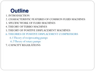
1. INTRODUCTION 2. CHARACTERISTIC FEATURES OF COMMON FLUID MACHINES 3. SPECIFIC WORK OF FLUID MACHINES 4. THEORY OF TURBO MACHINES 5. THEORY OF POSITIVE DISPLACEMENT MACHINES 5.1 Theory of reciprocating pumps 5.2 Theory of rotary pumps 6. THEORIES OF POSITIVE DISPLACEMENT COMPRESSORS 7. CAPACITY REGULATIONS
THEORY OF POSITIVE DISPLACEMENT MACHINES Reciprocating and rotary positive displacement pumps are common in the chemical and process industries. The characteristic features and operating principles of the most common positive displacement pumps are discussed previously. In this chapter the relation between their geometry and performance is discussed. 3
Theory Of Positive Displacement Pumps Positive Displacement Reciprocating Rotary -Screw -lobe -vane - Gear* -Piston -Plunger -Diaphragm
5.1 Theory Of Reciprocating Pumps Reciprocating pumps include:- Piston pumps Plunger pumps and Diaphragm pumps The operating principle of these pumps is the same. Therefore the theory is discussed based on just one of them, i.e., a piston pump. 5
7 1 4 2 5 3 6 Discharge Air bleed valve Relief valve Plunger Diaphragm Pumping chamber Hydraulic fluid Relief valve Suction Plunger Cylinder Figure Plunger pump 6
5.1.1 Capacity of Reciprocating Pumps The capacity of a reciprocating pump is determined by: the size of the cylinder the number of piston strokes or the speed of rotation of the crank shaft the number of cylinders and the number of actions (single acting and double acting). 7
A single acting-reciprocating pump is a pump with only one side of the piston acting on the liquid. When the two sides act we call it double acting. R R Figure 5.1a Single acting piston pump Figure 5.1b Double acting piston pump 8
a. Single acting pumps The capacity of a single acting reciprocating pump is the product of the displaced volume, the number of double strokes (rpm), and the volumetric efficiency as it is given 4 = 2 Q Sn D vol Where:- n= number of piston double strokes D=Inner diameter of the cylinder (bore diameter) S= piston stroke, vol= Volumetric efficiency Q= Capacity (Volume flow rate) = 2 S R 9
The volumetric efficiency takes into account leakage through clearances and suction and discharge valves during the suction stroke and vice versa. It is determined, in the course of pump tests, by measuring the actual volume of liquid delivered by the pump per unit time. Q = vol ' Q Q: Actual volume flow rate Q : Theoretical volume flow rate 10
For a reciprocating pump it is common to give the slip of the pump instead of the volumetric efficiency. The slip of the pump is the measure of the total volumetric loss of the pump given as a fraction of the theoretical capacity. The slip is given by:- vol =1 Slip = ' 2 Q Sn D 4 Normally vol = 0.7 to 0.97 11
b. Double acting pumps The capacity of a double acting pump is twice the capacity of the single acting minus the reduction in capacity due to the volume displaced by the connecting rod. Hence, 4 = 2 2 2 ( ) Q Sn d D vol Where:- d is the diameter of the rod R R Figure 5.1a Single acting piston pump Figure 5.1b Double acting piston pump 12
c. Multiple Cylinders If a pump has several cylinders of same size with their pistons actuated by a common crankshaft (multiplex pump), the pump capacity is calculated as the capacity developed by one times the number of pistons. Figure: multiplex pump 13
Example 5.1 The stroke length and bore diameter of a double acting single cylinder reciprocating pump are 30cm, and 35cm respectively. The diameter of the rod is 22mm.The speed of the crank is 60 rpm. Determine the capacity of the pump if the slip of the pump is 5%. 14
Example 5.2 The flow rate of a reciprocating pump that runs at 90 rpm is measured to be 38.2 m3/hr. The stroke length and the internal diameter of the cylinder are 24cm and 20cm respectively. Calculate the slip of the pump. 15
5.1.2 Suction and Discharge Pulsations in Reciprocating Pumps Since liquid is an incompressible medium the velocity of the liquid inside the cylinder of reciprocating pumps is the same as the velocity of the piston head. The velocity of the piston head, if it is actuated by crank, varies with the crank angle. Hence the velocity of the liquid inside the cylinder and consequently the capacity vary with the crank angle. Unless special steps are taken, the motion of the liquid in the suction and discharge pipes will be also non-uniform. It is this non-uniformity that we call pulsation. 16
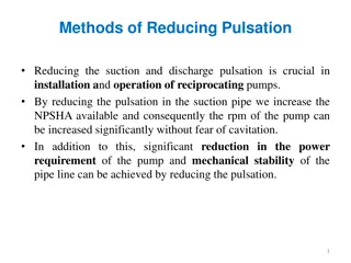
Pulsation causes several of problems in addition to the non- uniform delivery. It reduces the NPSHA significantly and to avoid cavitaions the pump should run at a reduced speed. It causes mechanical instability of the piping network. It also causes increased power consumption due to the acceleration head involved caused by variation in flow velocity. 17
The Velocity and Acceleration of the Flow Medium in Reciprocating Pumps L R x L+ R Figure 5.2 Geometric relations in a reciprocating pump 18
+ + = + sin2 2 2 cos x R L R L R = + 2 2 2 1 ( R cos ) sin x L L R 2 R = + 2 1 ( R cos ) 1 ( L 1 sin ) x 2 L The velocity of the piston head ) ( 1 dx d d / 1 2 2 = = + 2 sin 2 sin cos R vp R sin 2 2 L R 2 dt dt dt 2 sin = + 2 sin R 2 ( sin cos ) dx d v R 2 p = = + sin R vp 2 L 2 2 sin dt dt 2 2 2 sin L R 2 R 19
The ratio L/R is commonly in the range of 4:1 to 6:1. Lower L/R ratio causes high pulsation and larger L/R ratio results in large uneconomical power frame. 2 L R sin 2 Since 2 = + sin sin R vp R 2 / L When L/R >>1, the motion can be approximated by simple harmonic motion R vp= sin The Acceleration of the Piston Head (plunger) 2 d x cos L 2 R ap = = + 2 cos R 2 / dt ap= 2R L cos For simple harmonic i.e., R 20
Example 5.2 The flow rate of a reciprocating pump that runs at 90 rpm is measured to be 38.2 m3/hr. The stroke length and the internal diameter of the cylinder are 24cm and 20cm respectively. Calculate the slip of the pump. 21
Example 5.3 For the pump in Example 5.2 determine the flow rate and acceleration of the liquid in the cylinder of the pump at the beginning and middle of the suction stroke (1) assuming L>>R and (2) without the assumption in (1) and taking the length of the connecting rod to be 75cm. 22
The Acceleration Head of the Flow Medium in the Suction and Discharge Pipes Because of the acceleration of liquid in the cylinder the liquid in the suction and discharge pipes also accelerate. From the continuity equation, v A p A p v = = A v A v s p p s s s Where:- Ap= Cross -sectional Area of the piston head vp=velocity of the piston head As= Flow area of the suction pipe vs= velocity of the liquid in the suction pipe 23
Therefore the acceleration of the liquid in the suction pipe is given by v A dv p A p = = s a s dt s A dv A p p p = = a a s p A dt A s s A cos L 2 R p = + 2 cos R a s / A s 24
Similarly for the liquid in the discharge pipe A cos L 2 R p = + 2 cos R a d / A d Ad= Flow area of the discharge pipe For simple harmonic motion the accelerations of the liquid in the suction and discharge pipes are given by:- A A p s= cos R p 2 d= cos R 2 a a A A s d The specific work to accelerate the liquid through the suction and discharge pipes are given by ma L ma Ls = = = d d Y FL a L = = = s Y FL a L , a d d d d m , a s s s s m 25
ma L ma Ls = = = = = = d d Y FL a L s Y FL a L , , a d d d d a s s s s m m F=Force to accelerate the liquid Ya,s= The specific work to accelerate the liquid in the suction pipe Ya,d= The specific work to accelerate the liquid in the discharge pipe Ls= Portion of the suction pipe through which there is acceleration (pulsation) Ld= Portion of the discharge pipe through which there is acceleration m= Mass of liquid in consideration 26
A Hence, ma L p = Y a L = = = d d Y FL a L , a s p s A , a d d d d m s The acceleration head, ha=Ya /g is therefore A A p g = h a L p g = h a L , a d p d A , a s p s s A s 2 A R L cos 2 2 A R L cos 2 p d = + cos h p s = + cos h , a d / A g L R , a s / A g L R d s For simple harmonic motion A d 2 A R L g A s 2 A R L p d = cos h p s a = cos h , a d g , s 27
Example 5.4 The dimensions and speed of a single acting single cylinder reciprocating pump and the dimensions of the suction pipe are as given below. S= 32cm, D=30cm, ds= 2" (Diameter of suction pipe), n=50rpm, Ls= 5m Assume L/R>>1 and Determine the acceleration head of the liquid in the suction pipe at the beginning, middle and end of the suction stroke. 28
5.1.3 The Minimum Pressure for the Piston to Move in the Cylinder The piston or plunger of a reciprocating pump should apply a certain minimum pressure to move inside the cylinder. This pressure depends on:- The pump design Speed and the piping system and The flow medium 29
2 Ls hs 1 Figure A pumping system using reciprocating pump The relationship between the total mechanical energy of the flow medium at point 1 and 2 , is given by:- P P + = + + + 1 2 z z h h 1 2 a fs g g Where ha= acceleration head in the suction pipe hfs= friction head in the suction pipe 30
Therefore the pressure inside the cylinder, P2 can be calculated by:- h z z g g P P = 2 1 ( ) h 2 1 a fs Since most commonly P1=Patm P P = atm g 2 h h h s a fs g Similarly for the discharge stroke P P = d g 2 h h h d a fd g Note that during the discharge stroke ha < 0 since cos < 0 for >900 31
5.1.4 The Minimum Pressure to Open the Suction Valve P P = atm g 2 h h h s a fs g The maximum acceleration head is much larger than the maximum friction head. Therefore the minimum pressure occurs when the acceleration head is maximum, i.e. at =00. At this pressure the friction head is zero, since the velocity of the flow medium is zero. Hence, P P , 2 min g = atm g , h h max s a 32
For simple harmonic motion , with =00. 2 A R L p s = h , max as A s The minimum pressure to open the suction valve is:- 2 A R L P P p s , 2 min = atm g h s g A s 33
5.1.5 The Minimum Pressure to Open the Discharge Valve The minimum pressure during the discharge can be similarly calculated. The minimum pressure to open the discharge valve can be calculated using:- 2 A R L P P p d , 2 min = d g h d g A d 34
5.1.6 The Indicator Diagram The indicator diagram of a reciprocating pump shows the pressure variations in the cylinder and valve chest over the length of two piston strokes. The indicator diagram is used to calculate the work done by the pump during one complete suction and discharge stroke. 35
Theoretical Indicator Diagram As the piston moves to the right the pressure inside the cylinder is reduced and the suction valve is opened while the discharge valve is closed. The enclosed space of the cylinder is increased and is filled with liquid coming from the intake pipe through suction valve. 3 2 P Patm 4 1 1 S (Vpist) Figure 5.4 Theoretical Indicator Diagram of a Piston Pump 36
Discharge 3 2 P Suction closed v discharge open Suction open v discharge closed Patm 4 1 1 Suction S (Vpist) Figure 5.4 Theoretical Indicator Diagram of a Piston Pump 37
At this point, the pressure in the valve chest is below atmospheric, which is due to the hydraulic resistance of the suction line. The change in pressure over the whole length of rightward stroke of the piston is given by suction line 4-1. When the piston head assumes position 1, the piston reverses its direction of motion and the suction valve is automatically closed; the pressure in the valve chest builds up abruptly to its level P2. This process is shown by the vertical line 1-2. At the instant the pressure grows as high as P2 the pressure difference across the discharge valve overcomes the weight and tension of its spring, thus opening the valve. As the piston moves steadily from point 2 leftwards, the liquid is discharged at constant pressure P2. In the extreme left position the piston again reverse its direction of motion. The result is that the pressure in the valve chest drops abruptly along line 3-4, discharge valve is closed and the suction valve is opened. The pressure displacement diagram, referred to as indicator diagram, is completed. 38
The Indicator Power is the theoretical power of a reciprocating pump that can be calculated from the theoretical indicator diagram. Work done by the piston in any of the strokes can be given as Force = tan Work done Dis ce For the suction stroke W For the discharge stroke W 1= S P A 2= S P A 1 pist 2 pist The total work done in one complete cycle = + = W S ( ) P A P A W S P i pist 1 2 pist 39
For one revolution of shaft the work done by a single acting pump is:- W A P pist i = S Since V=Apist S, if the indicator diagram is constructed with volume as the horizontal axis the area of the indicator diagram ( the rectangle 1-2-3-4) is equal to the work done in one revolution. The indicator power can be calculated by multiplying the area of the indicator curve by the speed of rotation. It can also be noted that Q =Apist S n, hence the indicator power is equal to the product of the indicator pressure and the theoretical volume flow rate. i= i= ' Sn Q N P A N P i i pist 40
Brake Power and Useful Power The break power that should be delivered from the motor to the pump hence is, N N = i brake m Where:- m is the mechanical efficiency m = 0.9 to 0.95 Sn P A i pist = N brake m ' Q P = i N brake m 41
i i N = N The useful power N Where i is the internal efficiency which takes care of the hydraulic loss and leakage losses vol h i= h = 0.8 to 0.94 vol = 0.7 to 0.97 h = The overall efficiency is determine by vol m N Nbrake= The coupling power is determined by the formula QgH Nbrake= The efficiency of a piston pump is determined by experiment 42
Head of Reciprocating Pumps N = brake P i H Qg A Sn pist brake= N A Sn Q P P P i pist vol h m i i = = = h m h H Qg Qg g m m Therefore the head of a reciprocating pump can be obtained from the indicator pressure using:- i P = h H g 43
The Actual Indicator Diagram The main difference between the actual and theoretical indicator diagrams lies in the pressure fluctuations in the beginning of suction and discharge strokes, and the effect of the acceleration head which varies with crank angle. These fluctuations are caused by the effect inertia of the valve and the striking of the valves to their seats because of the intimate meeting of ground-in surfaces. Therefore when the discharge valve is being seated, the pressure in the valve chest must be raised to a level high enough to produce a force capable of taking the valve off its seat and overcoming its inertia. 44
2 3 1 Patm P 4 A(Vpist) Figure Actual indicator diagram of a piston pump As soon as the valve opens, the pressure in the valve chest falls off abruptly and the valve bobs rapidly up and down several times in the liquid flow, thus throttling the flow and causing the pressure in the valve chest to fluctuate, which accordingly affects the discharge line of the indicator diagram. The actual indicator diagrams are drawn using readings of indicators connected to pumps. 45
Cavitations in Reciprocating Pumps Calculation of the NPSHA should involve the acceleration head incase of reciprocating pumps. P P = A g T g NPSHA h e h fs s a Where:- ha is the acceleration head As it is already discussed the acceleration head is mostly much larger than the friction head, hence the cavitation condition is usually considered, for =0, when the acceleration head at the suction side is maximum, i.e. has=has,max. At this condition, hfs=0, and NPSHR=0, since the velocity of the flow medium at that instant is zero. 46
NPSHA Therefore to avoid cavitations, NPSHR Since NPSHR=0, no flow 0 NPSHR P P A g T g 0 e h , max s as 2 for =0 A R L P P p s 0 A g T g e s A s A L P P 2 S s A T e s RLsA g g p A L P P S s A T e s RLsA g g p A L P P 1 S s A T n e = 2 n s 2 RLsA g g p Note: Ls is the length of the suction pipe through which there is pulsation. 47
Performance Characteristics of Reciprocating Pumps The performance characteristic of reciprocating pumps is quite different from centrifugal pumps. As in the case of centrifugal pumps, the performance characteristics is commonly described as a graph. In such cases it is called characteristic curve Theoretical Performance Characteristics For a given reciprocating pump with a given geometry and speed the head does not depend on the theoretical capacity and vice versa. The theoretical capacity, for a single acting single cylinder-reciprocating pump is given by :- = ' 2 Q Sn D 4 48
H-Q curves Constant diameter (D) and stroke length (S), different speeds This curve is especially important in flow rate regulation by varying speed. The mean volume flow rate is directly proportional to the speed. Therefore for three speeds n1<n2<n3, the flow rate becomes: ' ' 2 ' 3 = = = 2 2 2 Q Q Q Sn Sn Sn D D D 1 2 3 1 4 4 4 H n1 n2 n3 Q 2 Q 3 Q 1 Q Figure : Theoretical Characteristic Curve of a Reciprocating Pump for different speeds 49
Constant Diameter (D) and speed (n) and various strokes (S) The theoretical performance characteristics for different stroke lengths are derived in similar fashion and the curves are similar to those in previous figure. 50


