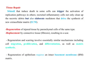
Advancements in Dye-Sensitized Photoelectrochemical Cells
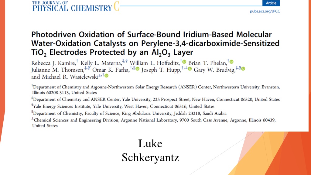
History traces the development of photoelectrochemical cells since 1972, highlighting the progress, challenges, and state-of-the-art dyes used, with an emphasis on improving performance through innovative solutions like Al2O3 layers. Key issues such as dye degradation and electron-hole recombination are discussed, alongside insights into breaking down DSPECs and studying their behavior through steady-state UV-Vis absorption and electrochemistry techniques.

Download Presentation

Please find below an Image/Link to download the presentation.
The content on the website is provided AS IS for your information and personal use only. It may not be sold, licensed, or shared on other websites without obtaining consent from the author. Download presentation by click this link. If you encounter any issues during the download, it is possible that the publisher has removed the file from their server.
E N D
Presentation Transcript
l Luke Schkeryantz
History of PhotoElectroChemical cells First reported in 1972 Fujishima and Honda, Nature, 238, 37-38 Heavily invested in the 70's and 80's, progress slow Field revitalized in 90's and continues today with separation of light absorption and redox active components of the cell
Dye-Sensitized PhotoElectroChemical Cells Nearly all DSPECs use TiO2 as photoanodes Ruthenium based dyes are most common Improving anchoring groups of dye J. Phys. Chem. C 2013, 117, 14526 14533
State of the Art Dyes Photoelectrodes J. Phys. Chem. Lett. 2015, 6, 3213 3217. ACS Nano 2012, 6, 6185 6196 J. Phys. Chem. C. 2012, 116, 4892 4902 J. Mater. Chem. A. 2016, 4, 2969 2975
Problems with DSPECs Paper identifies two main problems Degradation of dye molecule Fast electron hole recombination time Proposed solution Layer of Al2O3
Breaking Down DSPECs Perylene-3,4-dicarboximide (PMI or dye) IrIr (dimeric catalyst) The mode of binding is unknown for this molecule IrSil (monomeric catalyst)
Steady-State UV-Vis Absorption ALD refers to Atomic Layer Deposition, or growth of Al2O3 layer Blue-shift for first few cycles of ALD Disaggregation of PMI Red-shift for additional cycles of ALD More rigid environment for the PMI Degradation monitored by UV-Vis No ALD = Major loss of PMI in 2 weeks in light and air More ALD = Less loss 30 Full cycles = Low loss even after 3 months
Electrochemistry Performed with Ag/AgCl reference electrode Pt counter electrode All values given against NHE (normal hydrogen electrode)
Photoelectrochemistry Linear sweep voltammetry (LSV) was performed to study the response of the films to an applied bias under light (420 nm) An increased photocurrent was observed upon addition of Al2O3 indicating the charge recombination benefits outweighed the negative impact on electron injection The photocurrent changed with addition of the catalysts IrIr showed lower photocurrent, IrSil higher IrIr due to faster recombination, further supported by enhanced photocurrent with more ALD IrSil due to the long linker between the Ir metal center and the electrode surface IrIr displays higher catalyst functionality than IrSil under purely electrochemical conditions
Transient Absorption Spectroscopy Irradiated initially with 495 nm Excitation of PMI causes ground state bleach (GSB) at 430-575nm, stimulated emission (SE) at 575nm and singlet excited state absorption (1*PMI) at 680nm About 14% of excited PMI units do not inject electrons into TiO2 ( 1) The rest however do inject electrons on a time scale of 1-10 ps ( 2) Demonstrated by rapid decay of SE and (1*PMI) bands 600 nm band represents a Stark shift of PMI ground state absorption induced by electron injection Substantially lowered in systems with ALD (approximately 1.6 times slower) Rate slows with as little as 5 cycles of ALD and does not further slow with additional ALD Decay of absorption at 600 nm represents charge recombination
Transient Absorption Spectroscopy (cont.) Authors expected a slower electron injection rate ( 2) would also result in a longer electron recombination ( 3) Not the case with systems with no catalyst ALD may protect against charge recombination with solvent
Catalyst Kinetics No direct observation of catalyst possible with UV-Vis (low absorption by these Ir species) Kinetics elucidated by comparison to analogous system with no catalyst More rapid rise of Stark shift and faster decay of 1*PMI and SE in cells with IrIr Indicates faster electron injection and recombination Authors argues this indicates ( 4) and ( 6) are occurring rapidly (although diminishes with greater ALD) Potentially ( 5) is implicated in this spectra, but not conclusive In contrast the system with IrSil are almost indistinguishable from the no catalyst cell ( 4, 6) is longer and non competitive with ( 2) Pathway ( 2, 5) is dominant in oxidation of the catalyst ( 7) for both catalyst systems increases with additional ALD
Catalyst Testing Generator-Collector Method biased by 0.51V and -0.49 V respectively Both cells with catalyst and without were tested Illuminated by 410 nm light Counter electrode = Pt Mesh Faradaic efficiency of 18% and 22% w/o and with catalyst Both catalysts performed similarly Lack of difference between systems indicates little oxidation performed by catalyst
Conclusions Achievements ALD layer of Al2O3 protects dye molecules from degradation and slows charge recombination Concerns Negligible improvement in catalysis yields with catalyst applied Inconsistent reasoning on various points Contradiction between photoelectrochemistry and catalysis Future Work Studying intermediate charge transfer steps further Investigate new conditions to improve rate of catalyst oxidation