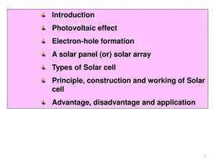
Introduction to Dye Sensitized Solar Cells
Dye Sensitized Solar Cells, pioneered in 1991, offer cost-effective and efficient solar energy conversion. Comprising a photoanode with a dye sensitizer, electrolyte, and counter electrode, these cells operate by converting sunlight into usable electrical energy. The cells can be enhanced for higher efficiency by optimizing factors like Voc and Jsc.

Download Presentation

Please find below an Image/Link to download the presentation.
The content on the website is provided AS IS for your information and personal use only. It may not be sold, licensed, or shared on other websites without obtaining consent from the author. Download presentation by click this link. If you encounter any issues during the download, it is possible that the publisher has removed the file from their server.
E N D
Presentation Transcript
Lecture-16 Dye Sensitized Solar Cells Dye Sensitized Solar Cells Dr. Satyanarayan Dhal
Upto Upto How many Days , Fossil Fuel ? How many Days , Fossil Fuel ? Oil 40 Yrs Natural Gas 60 Years Coal 200 Years
Why Dye Sensitized Solar Cell? Why Dye Sensitized Solar Cell? Cost effective Inexpensive Simple Fabrication Easy to print dye-sensitized solar cells on flexible substrates Work better during dark. Excellent for Windows (Indoor) This Photo by Unknown Author is licensed under CC BY-SA
Historical Background Historical Background 1. Initiated in 2. 1991 : O Regan and Gratzel 2014 (13%) 1991 (7 %)
Structure Structure Components : 1. photoanode made up of a mesoporous oxide layer (typically, TiO2) deposited on a TCO substrate. 2. Monolayer of dye sensitizer covalently bonded to the surface of the TiO2 layer. 3. Electrolyte containing redox couple in an organic solvent. 4. Counter electrode made of a Pt coated conductive glass Substrate.
How it operates ? How it operates ? When the sunlight strikes the solar cell. 1. Dye sensitizers on the surface of TiO2 film get excited and the electrons in turn get injected into the conduction band of TiO2. 2. Within the TiO2 film, the injected electrons diffuse all the way through the mesoporous film to the anode and are utilized to do useful work at the external load. 3. Electrons are collected by the electrolyte at counter electrode which in turn are absorbed to regenerate the dye sensitizer.
How it operates ? How it operates ? When the sunlight strikes the solar cell. 1. (Voc) is determined by the potential difference between Fermi-level of electrons in the TiO2 film and redox potential of electrolyte. 2. (Jsc) is determined based on the incident light harvest efficiency (LHE), charge injection and collection efficiencies.
How we can raise efficiency ? How we can raise efficiency ? 1. How to obtain high Voc ? - Using Co(II/III) redox couple which has more positive redox potential and therefore increases the potential difference. 2. How to obtain high Jsc? - Using panchromatic dye sensitizers which can absorb broad sunlight covering visible to the near-infrared range in solar spectrum.
Cosensitization Cosensitization we can raise efficiency! we can raise efficiency! 1. A sensitizer absorbs all incident light from the visible to the near-IR region of solar spectrum up to the wavelength of approximately 920 nm. 2. Ruthenium(II)-polypyridyl complexes such as N3, N719, N749, and black dyes have been synthesized. 3. Drawbacks: High cost. Limited amount of noble metals. Sophisticated synthesis and purification steps. 1. Metal-free organic dyes can replace Ru (II) based dyes, due to their intrinsic high molar absorptivity and broad absorption by co-sensitization approach.
Cosensitization Cosensitization we can raise efficiency! we can raise efficiency! 1. Co-sensitization complementary dyes (i.e., blue and red absorbing sensitizers) into a DSSC. 2. Cost effective route sensitization. 3. Also involves plural organic dyes provided that each of them has different absorption wavelengths. 4. Like: triple-dye-sensitization using organic dyes; 1. How to select dye-cosensitizer selection ? = Combining two spectrum to the panchromatic 2. Ans: Chemical compatibility between dye co- sensitizers, and a high molecular extinction coefficient. This Photo by Unknown Author is licensed under CC BY
Light scattering Light scattering 1. Photosensitizers with improved spectral response at the low-energetic solar spectrum is not successful. 2. Reason : Dye molecules with high red absorbance have lower excited-state excess free energy; lowering the quantum yield for charge injection. 3. Solution : Increase the film thickness beyond 10 m. 4. Increased electron recombination rate = photocurrent. 5. 6. Increase the path length of light by enhancing light scattering in the TiO2 films. transport marginal length decrease and in This Photo by Unknown Author is licensed under CC BY
Light scattering Light scattering 1. To increase the light path length, Usami et al. proposed a structure that effectively confines incident light in the thinner cells by multiple scattering. 2. Incorporate larger particles as effective light scatterers. 3. Coating a scattering-layer on the top of active layer. 4. 3D TiO2 nanostructures such as network of nanofibers , nanotube arrays (TNAs) , submicron sized hollow spheres, and aggregates have been developed to enhance light scattering. This Photo by Unknown Author is licensed under CC BY Usami A. Theoretical simulations of optical confinement in dye-sensitized nanocrystalline solar cells. Sol Energy Mater Sol Cells 2000;64:73 83.
Transparent electrodes Transparent electrodes 1. A DSSC can be operated using either frontside or backside illumination. 2. In a frontside illumination arrangement, the light source is on the substrate side of the device, and for a backside illumination, the source is on the electrolyte side. 3. A DSSC consisting of nanoparticulate film generally provides superior light-conversion efficiency for frontside illumination, which is due to the fact that the most efficient charge separation takes place close to the back contact. This Photo by Unknown Author is licensed under CC BY Usami A. Theoretical simulations of optical confinement in dye-sensitized nanocrystalline solar cells. Sol Energy Mater Sol Cells 2000;64:73 83.
Transparent electrodes Transparent electrodes 1. For back-illuminated DSSCs, a counter electrode of high transparency is needed. 2. Backside illumination is not optimal in DSSCs since the platinized counter electrode partially reflects light. 3. Developing optically transparent counter electrode is beneficial for certain practical applications, like windows, roof panels, or various decorative installations. This Photo by Unknown Author is licensed under CC BY
Transparent electrodes Transparent electrodes 1. Graphene and its composites are alternatives to Pt for high transparent counter electrode and good electrocatalytic activity. 2. Ultrapure carbon nanotubes directly transferred to a film could achieve a transparency over 90% at 550 nm wavelength. 3. Graphite substrate with activated carbon was found to have good flexibility and high catalytic property. This Photo by Unknown Author is licensed under CC BY
Novel structured DSSC devices Novel structured DSSC devices 1. Various kinds are there : 2. P-type, tandem, hybrid, wire format, solid and quasi- solid state DSSCs. 3. Quantum dot sensitized solar cell (QDSSC): The dye replaced by a quantum dot. 4. Liquid electrolyte can be gelated (quasi-solid-state DSSC) or replaced by a solid hole conductor (solid- state DSSC). 5. Tandem DSSC is particularly attractive due to its capability of attaining high power conversion efficiency. This Photo by Unknown Author is licensed under CC BY-SA
P P- -type DSSC type DSSC 1. Operates in an inverse mode where dye-excitation is followed by rapid electron transfer from p-type semiconductor (p-SC) to the dye sensitizer. 2. When light is absorbed, the excited sensitizer injects a hole into valence band of semiconductor, leading to the reduction of the sensitizer. 3. The injected holes diffuse through the back (TCO) and then in turn pass through the external circuit and reach the counter electrode where they finally oxidize the redox mediator back to its original state.
P P- -type DSSC type DSSC 1. The optical excitation of the absorbed dye is followed by 2. (a) electron transfer from the excited dye to the oxidized species (I3 ) in the electrolyte, 3. (b) electron transfer from valence band of p-type NiO to the HOMO level of dye.
P P- -type DSSC type DSSC 1. The tandem DSSCs can enhance the full-spectrum light harvesting by stacking multiple dyes of complementary absorption characteristics. 2. Theoretical limit of tandem DSSC efficiency could reach as high as 43% under STC, which is much higher than the 30% of conventional DSSCs with one photoactive dye-sensitized electrode. 3. Tandem DSSCs can be categorized into three groups: ;a stack of preassembled DSSC devices; a combination of dye-sensitized photocathodes with dye-sensitized photoanodes combination of complete dye-sensitized solar cells with other types of solar cells (hybrid). (pn-DSSCs); a
P P- -type DSSC type DSSC 1. The simplest tandem structure consists of a top DSSC stacked on a bottom DSSC. 2. Two cells are either series or parallel-connected to form a tandem DSSC, namely, series-connected (ST- DSSC) or parallel connected T-DSSCs (PT-DSSC). 3. For ST-DSSCs, the short-circuit photocurrent density (Jsc) of the top and bottom cells should be same, whereas for PT-DSSCs the open-circuit voltage (Voc) of the top and bottom cells should be identical. 4. Shorter-wavelength photon carries higher energy than longer-wavelength photon, series connected cells could fully utilize this characteristic to achieve a higher opencircuit voltage (Voc).
P P- -type DSSC type DSSC 1. It is relatively easy for parallel connected cells to match Voc values by adjusting top cell, which in turn maximize the short-circuit photocurrent density (Jsc).