Understanding Hydraulic Cylinders and Their Applications
Cylinders are linear actuators converting hydraulic power into mechanical power for pulling, pushing, and pressing tasks. They can be single-acting or double-acting, with specific designs for different applications. Ram-type cylinders offer stability for heavy loads, and double-acting cylinders are versatile for applications requiring power in both directions. Learn about the construction, components, and calculations involved in hydraulic cylinders' operation and use.

Download Presentation

Please find below an Image/Link to download the presentation.
The content on the website is provided AS IS for your information and personal use only. It may not be sold, licensed, or shared on other websites without obtaining consent from the author. Download presentation by click this link. If you encounter any issues during the download, it is possible that the publisher has removed the file from their server.
E N D
Presentation Transcript
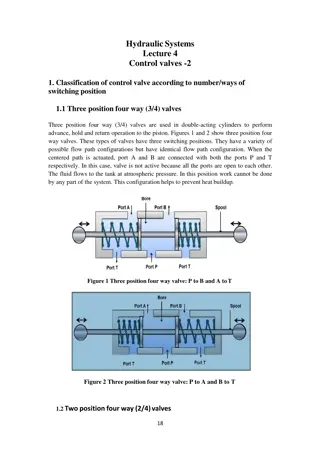
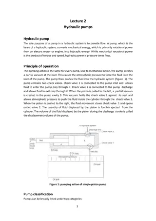
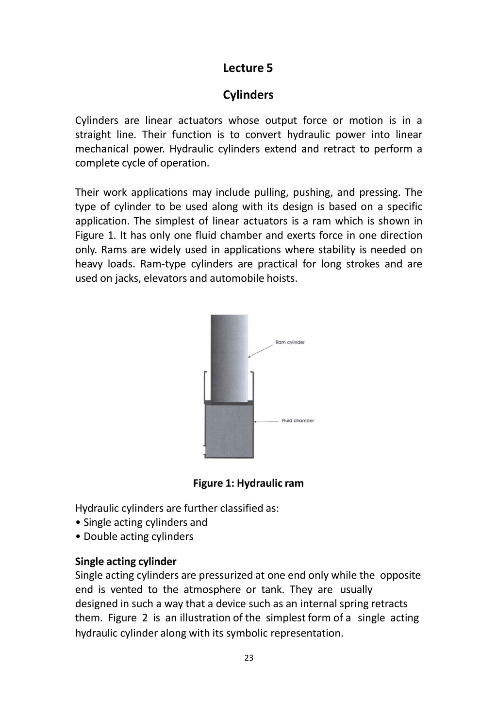
Lecture5 Cylinders Cylinders are linear actuators whose output force or motion is in a straight line. Their function is to convert hydraulic power into linear mechanical power. Hydraulic cylinders extend and retract to perform a completecycle of operation. Their work applications may include pulling, pushing, and pressing. The type of cylinder to be used along with its design is based on a specific application. The simplest of linear actuators is a ram which is shown in Figure 1. It has only one fluid chamber and exerts force in one direction only. Rams are widely used in applications where stability is needed on heavy loads. Ram-type cylinders are practical for long strokes and are used on jacks, elevatorsand automobilehoists. Figure 1: Hydraulicram Hydraulic cylinders are further classifiedas: Single acting cylindersand Double acting cylinders Single acting cylinder Single acting cylinders are pressurized at one end only while the opposite end is vented to the atmosphere or tank. They are usually designed in such a way that a device such as an internal spring retracts them. Figure 2 is an illustration of the simplest form of a single acting hydraulic cylinder along with its symbolic representation. 23
A single acting hydraulic cylinder consists of a piston inside a cylindrical housing called a barrel. Attached to one end of the piston is a rod, which extends outside one end of the cylinder (rod end). At the other end (blank end) is a port for the entrance and exit of oil. Blindend Piston Drain Figure 2: Single acting hydraulic cylinder Double acting cylinder Double acting cylinders are the most commonly used cylinders in hydraulic applications. Here pressure can be applied to either port giving power in both directions. Figure 3 shows the typical construction of a double acting cylinder. The cylinder consistsoffive basicparts: two end 24
caps (a base cap and a bearing cap) with port connections, a cylinder barrel, a piston and the rod itself. This basic construction provides for simple manufacture as the end caps and pistons remain the same for different lengths of the same diameter cylinder. The end caps can be secured to the barrel by welding, through tie rods or by threaded connections. 25
Figure 3: Construction of a double actingcylinder A hydraulic cylinder is used to compress a car body down to a bale size in 10 s. The operation requires a 10 ft stroke (S) and a force (Pbad) of 8000 lb. If a 1000 psi pressure (P) pump is selected, find (a) The required piston area (b) The necessary pump flow rate (c) The hydraulic horsepower delivered by the cylinder Solution: Here Fload is the force required to crush the car for which the pump used can deliver a pressure of 1000 psi. So, to get the area of the piston required to take this load, (a)Force = PxA so P= Fload /A= 8000/1000= 8sq.in. (b)The volumetric displacement of the cylinder equals the fluid volume swept by the cylinder during its stroke length (5) while the required pump flow rate equals the volumetric displacement divided by the time required forthe stroke. So, G(ftVs) = (AxS)/t= ((8/144) X10)/10 = 0.056 ft3/s 1 ft3/s = 448gpm So 26
= 448x0.056 = 25.1gpm In order to calculate the power delivered we will use the equation Hp=[P(psi)xQ(gpm)]/1714 This has been derived by using the conversion factors, keeping in view the basic Power-energy equation which is Power =Energy/Time So Hp = (1000x25.1)/1714 = 14.6hp This is the theoretical horsepower delivered by the cylinder assuming its efficiency to be 100%. Then, to calculate the actual hp, this should be multiplied by the efficiencyspecified by the manufacturer. 27


 with port connections, a")