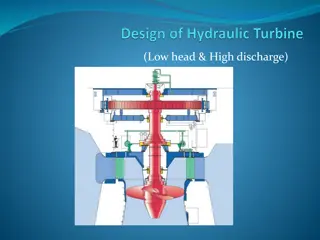
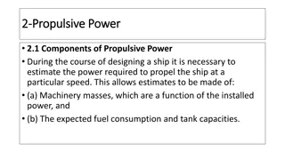
Understanding Wind Turbine Wakes for Optimal Farm Design

Optimizing wind farm design and operation involves analyzing wind turbine wakes to minimize power loss and ensure the safety and efficiency of turbines. Differentiating between near and far wakes, determining suitable spacing between turbines, and assessing wake size are crucial factors in maximizing power output and reducing fatigue loads. Computational Fluid Dynamics (CFD) techniques play a key role in simulating wake flows and optimizing wind farm layouts.

Download Presentation

Please find below an Image/Link to download the presentation.
The content on the website is provided AS IS for your information and personal use only. It may not be sold, licensed, or shared on other websites without obtaining consent from the author. Download presentation by click this link. If you encounter any issues during the download, it is possible that the publisher has removed the file from their server.
E N D
Presentation Transcript
Analysis of Wind Turbines Wakes P M V Subbarao Professor Mechanical Engineering Department Clues for Selection Clues for Selection of Suitable Spacing among of Suitable Spacing among WTs........ WTs........
Initial Remarks Optimizing the design and operation of wind farms requires understanding the complex interaction between atmospheric boundary layer flow and wind turbines. Most important phenomena to be deeply understood is; the structure of wind turbine wakes. The wakes are responsible for a reduction in wind velocity and an increase in fluctuations. This leads to a reduction in power output and an increase in fatigue loads in wind farms. CFD techniques with different degrees of complexity and accuracy can be applied to simulate wind turbine wake flows. All the CFD models need a significant amount of information for selection of domain, boundary conditions, grid size etc., their assessment and optimization.
Betz View of Wind Turbine Wakefield ( ) a = 1 u V ( ) a 2 = 1 u V 1
Description of HA Wind Turbine Wakefield Wind turbine wakes are classified into two types: Near Wake: The near wake is the region where the turbine geometry directly disturbs the wind. Far wake: The far wake is the region past the near wake
Need for Wake Analysis : to Minimize Power Loss It is very important to determine the optimum distance between neighbouring turbines, when developing wind farms. A too large distance will result in lower capacity of A wind farm and higher installation cost. A too short distance will result in lower power per turbine and increased fatigue problems for turbines located in the wake of other turbines.
Need for Wake Analysis : Safety of WTs Fatigue is in particular a problem for the second turbine in a row. The downstream turbine faces a high potential risk. Being hit by the tip vortices from the turbines located at the front of the wind farm. It is important to determine the lifetime of the tip vortices and the parameters that govern their breakdown into multiple small-scale vortices. This location is called as Fully Turbulent wake zone and no danger of high fatigue. However, velocity deficit is significant.
Size Estimations for WT Wakefield Near wake region is generally from the turbine to almost two to three rotor diameters downstream. It is very difficult to develop comprehensive understanding of near wake. This is due to the fact that there exist shear layers and a region of very low velocities in near wake. In the far wake, two main mechanisms defining flow conditions are convection and turbulent diffusion.
Presence of Shear layers in WT Near Wake Shear Layer The shear layer is an intermediate layer generated by the velocity difference between the air outside and inside of the wake. This shear layer contains strong velocity gradients and grows towards downstream. The rate of growth is much faster in near wake THAN far wake regions.
The WT Wake Mysteries Unravelled by Betz and Others p , V p , V V p , p pups = p p near, ds p p near, ds
Simplified (Linear) Kinematics of Near WT Wakefield p , p , V p , V V p pups p pids = p pds
Models for Wind Turbine Wakefield Integral Wake Models
Kinematic models for Fullwake Kinematic models are based on modelling of self-similar velocity deficit profiles. Kinematic wake models employ only the momentum equation to model the radially averaged velocity deficit of the wake. These models ignore the evolution of turbulence intensity in the wake behind a turbine. Three popular Kinematic Models: Jensen's fullwake model Larsen's model Frandsen's model V V & p ( ) r u1 p
Simplified Schematic Models for WT Wake scalar determines how quickly the wake expands with distance and it is defined as: V V ( ) r u1 = + r x r R 1 5 . 0 = z ln z 0 where z is the hub height of the turbine generating the wake and z0is a constant called surface roughness, which depends on the terrain characteristics.
Jensen's Fullwake model This model redefines the boundary of the control volume of a WT. Jensen s CV is the sum of CV affected by the WT and the surrounding compensating the velocity deficit. This is called the Jensen s Fullwake model According to this model assumes the fullwake is continuously linearly expanding. This is a linearly expanding wake with a velocity deficit that is only dependent on the distance behind the rotor.
Jensens View of Fullwake Jensen treated the wake behind the wind turbine as a turbulent wake which considers the contribution of all eddies or vortices present in the CV/wake. The wake model is derived by conserving the momentum downstream of the wind turbine. The velocity in the wake is given as a function of downstream distance from the turbine hub.
Jensen Single Fullwake Model V V V Awake u1 Uwake Arotor Rr ( ( ) x ) ( )wake u x + = rotor A u wake A rotor A V wake A 1 The law of conservation of momentum implies that the radius of wake(r) behind the turbine expands linearly with respect to down wind distance(D). Law of conservation of mass for wind turbine wake:
The velocity deficit V -u1is defined as final velocity deficit generated by the wind turbine to reach p . The velocity deficit depends on the power absorbed by the rotor. This can be calculated by using appropriate momentum theory and measured value of CT. Betz Theory: ( = a u 2 1 1 ) V ( ) a = 4 1 CT a
Velocity Deficit : BEM with Dual Induction Theory V 2 V u Bc 2 = 1 a = = a r 2 ( ) 1 1 a = tan ( ) + a r ( ) 2 tip r 1 U a ( ) + cos sin F C C rdr l d sin F T hub r = = = N C T 1 1 1 2 2 2 V A V A V A 2 2 2 0 0 0
Velocity Deficit : Fluid Dynamics Model The axial induction factor (of rotor) a & b are defined as: ( ) b ( ) a = 1 u V b 2 1 b 2 b a 1 0 = 1 a ) ( 2 4 R tip r ( ) rdr 2 2 F b b V 0 F T hub r = = = N C T 1 1 1 2 2 2 V A V A V A 2 2 2 0 0 0
Jensen Cone Model for Wake of A HAWT As mentioned before Jensen Model assumes that the wake downstream expands linearly. Thus, the path tracing by the wind downstream follows the conical shape of disturbance. The radius of the cone can be estimated by using the following equation: V V V Awake u1 Uwake Arotor Rr ( ) x = + 1 r R The dimensionless scalar , known as decay constant. w rotor


 Kinematics of Near")