Cutting-Edge Installation Vessel Designs and Challenges in Offshore Wind Farms
Explore innovative vessel designs utilized in offshore wind farm installations, along with challenges faced in the industry. Discover key partners, vessel concepts, operational phases, and strategies to enhance efficiency and reduce costs. Overcome obstacles related to turbine installation, weather conditions, and operational limitations for sustainable offshore energy production.

Download Presentation

Please find below an Image/Link to download the presentation.
The content on the website is provided AS IS for your information and personal use only. It may not be sold, licensed, or shared on other websites without obtaining consent from the author. Download presentation by click this link. If you encounter any issues during the download, it is possible that the publisher has removed the file from their server.
E N D
Presentation Transcript
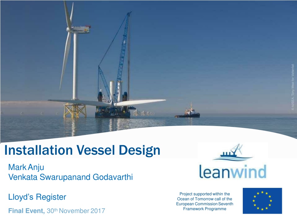
Installation Vessel Design MarkAnju Venkata Swarupanand Godavarthi Project supported within the Ocean of Tomorrow call of the European CommissionSeventh Framework Programme Lloyd s Register Final Event, 30th November2017
Some of Our Partners Partners Include: Operators Vessel Owners Simulation Specialists Research Institutions
Variety of Vessels Operating for Windfarms INSTALLATION VESSEL O & M VESSEL Installation Vessels O&M Vessels Anchor Handling / Supply Vessel Crew Transfer Vessel Offshore Tug/Supply Vessel Platform Standy SafetyVessel Research/Survey Vessel Accommodation Vessel Diving Support Vessel Pipe Laying Vessel Cable Laying Vessel etc .
Installation Vessels Foundation Installation vessels Turbine Installation Vessels
Challenges for Installation Vessel 3 4 5 6 7 8 9 1 2 TP Transitto site Positioning on site Foundation handling Transit to supplyport Turbine installation Crew change Mobilisation Load-out installation Increased demand for larger wind turbines Farms growing further offshore Limitation of offshore lifts Operating constraints due to meteorological conditions Improve weather monitoring and decision support system Optimise the number and size of turbines loaded per trip Decrease offshore operation duration Reduce fuel consumption and improve energy efficiency
Vessel Concepts Design Study Ship-shaped, floating self-propelled, DP-stabilised vessel specialised for foundation installation (FTIV) Ship-shaped, self-propelled and self-elevated vessel specialised for foundation installation (FTIJ) Ship-shaped, self-propelled and self-elevated vessel specialised for turbine installation (WTIJ)
Concept Selection Process Design implications Importan cefactor Location Sub-criteria VESSELCONCEPT Operational phases& tasks Ranking Factored Types Reduce cost& time Carry bigger turbines Wide weather window Optimised for site & transitop. s Average T imeincurred or saved per turbine Cost incurredor saved per turbine Factor Factored #1FTIV 2 2 2 1 1.75 SPIV (Jack up vessel) specialised for turbine installation -0.2 -0.6 1. #2FTIJ 2 1 3 2 2 Deck seafastening system for components/equipm ent Crane liftfor components Component positioningand fixing Ballastingfor jacking / submerging procedure Ballasting fortrim Case 0 South Knock 0.3 0.9 Mobilisation 3 #3WTIJ 3 3 3 3 3 Load-out Operational Criteria 5 -0.8 -4 -0.5 -2.5 1- Lesslikely 2-Likely 3-Highly likely 4 -0.8 -3.2 -0.5 -2 2 -0.2 -0.4 -0.1 -0.2 2 0 0 -0.1 -0.2 Number/size of turbinecomponents 4 -0.9 -3.6 -0.5 -2 Transit tosite Transitspeed TransitHs Transit wind speed 3 4 3 -0.2 -0.5 -0.1 -0.6 -2 -0.3 -0.2 -0.2 -0.5 -0.6 -0.8 -1.5 Ship-shaped, self propelled and self- elevated vessel specialised for turbine installation (WTIJ) Route 3 3 3 -0.2 0 -0.2 -0.6 0 -0.6 0 0 0 0 Positioning on site DP operations Jacking, hull elevation,pre- loading Jack-down Lifting and Handling -0.4 -1.2 3 5 -0.1 0.7 -0.3 3.5 -0.4 0.4 -1.2 2 Foundation handling Foundation Installation Positioning / Upendingand Hammering Lifting and grouting 4 0.7 2.8 0.7 2.8 TPInstallation 3 0.5 1.5 0.4 1.2 Turbine Installation Seafastenings Techniciantransfer to TP Lifting components and assembly 3 5 -0.2 -0.8 -0.6 -4 0.3 -0.2 0.9 -1 5 -1 -5 -0.8 -4 Helicopter operations for crew change Crew change 1 -0.1 -0.1 0.1 0.1
WTIJ Design Selection Key parameters Cargo Selection & Capacity Vessel Economics CAPEX & OPEX Time reduction Port and Site restrictions Crane operations
Vessel Economics Turbine Selection Hundreds 2.0 Time to install (days) 150NM Effective Installation cost per turbine Thousands 100NM 1.8 480.00 50NM 5, 474.48 20NM 470.00 Sample Vessels Installation cost per turbine 460.00 1.6 5 6 7 8 9 10 11 450.00 No of turbines pervessel 440.00 Installation time 6, 435.56 430.00 11, 428.71 48 46 44 42 40 38 36 34 420.00 Millions 9, 414.55 Installation Cost 7, 410.38 410.00 8, 406.10 150NM 400.00 100NM 8, 392.09 50NM 390.00 4 6 10 12 8 20NM TurbineNumber 5 6 7 8 9 10 11 No of turbines per vessel Installation cost Courtesy: Geosea Maintenance (DEME Group)
Installation Vessel Design Features Ship type self elevating vessel (168.5x50x12) Pedestal Crane (Max. 1500t) Dual Fuel Engine Cargo Capacity (9000 t)
Examples of Concept Design Activities Hull Form Design, Optimisation & CFD Analysis Leg Length Calculation DP Calculation Conical spudcan for easy assembly Stability Calculations SEA G OING Dynamic Positioning Turbine In stallation Jacking up POWER kW load factor diversity factor power kW diversity factor power kW diversity factor power kW diversity factor power kW AccomodationLoad 843 TOTAL 2168 823 936 825 Main Crane Legs Forward crane AftCrane DP bow thrusters 3300CP x 2 Azimuths AftUS 355-P50 x 4 5000 20000 200 150 5110 14800 0 0 47428 Electric Load Calculations 0.8 0.8 0.8 0.8 1 1 0 0 0 0 0 0 0 0 0 0 0 0 0 0 0 0 1 0 0 0 0 0.7 0 0.2 0.2 0 0 0 0 2800 0 32 24 0 0 0 0 3699 0 0 0.9 0 0 0 0 0 0 14400 0 0 0 0 0 0 15225 5110 1480 0 0 7526 0.6 0 0 8880 0 0 9703 0.1 0 0 TOTAL Structural Calculations
Key Elements of WTIJ Concept Pure LNG propulsion system Capable to operate in all regions of ECA Capable to carry and mount 8 units of 8MW (or 7 pieces of 10MW) wind turbines (for 10MW subject to design features) Capable to install 32 wind turbines with 4 visits without refuelling Capable to install wind turbines with 1500-ton main crane or to install both wind turbines and monopile foundations (4 pcs) with 2000-ton main crane Capable to operate under higher wind speed conditions via high wind boom lock system for installation of suspended weights Environmental Regularity Number = (99, 99, 98, 98, 84) for dynamic positioning operations with existing propulsion and thruster system 6040 m2 free main deck area optimized for fastinstallation 70 person capacity (crew + technicians)
Simulation Activities - Scope Simulator based studies supporting: Feasibility Studies for innovative design solutions Development of Operational Procedures Training of crews and operators Development of thrust allocation strategies Development and tuning of DP system Development of combined/integrated operational procedures for DP and crane operations Determination of weather windows for safe operation
Leanwind Project Simulator Demo K-Sim simulator model consisting of Vessel hydro dynamical model based on design principles Corresponding K-Pos DP SW with current off theshelf wind turbine installation and service functionality Installation crane 4-leg jacking system Deck layout for 8 x 8MW turbines Operator environment forDP, jacking operator and crane operator
Commercial Benefits for LR Update of LR rules and guidance Testing impacts of regulatory changes Opportunitiesto Class New Build/TOC Access to information regarding corporate plans for new innovation and cost reduction Installation vessel concept design support LR Strategic Offshore Wind market entry/design optimisation for vessel owners Wind Turbine Foundation Certification (Design and Mnf Review) O&M vessel operations support IRIS Scour modelling on wind farms
Rules and guidance Classification of Wind Farm Service Vessels Guidance Notes for the Classification of WindFarm Service Vessels The growing market for offshore wind farms has created an industry requirement for service vessels to support the construction and installation of the associated wind turbines. Typically these vessels are engaged in ferrying workers and light cargoes to the wind turbines for construction and routine maintenance. This guidance note is designed to assist designers, builders, operators and owners wishing to Class their Wind Farm Service Vessels with Lloyd s Register (hereinafter referred to as LR). For the Classification of these vessels, all parts the LR Rules and Regulations for the Classification of Special Service Craft (hereinafter referred to as the Rules for Special Service Craft) are to be applied
Rules and Guidance Guidance Notes for Wind Turbine Installation Vessels This Guidance Note provides summary information for designers and operators concerning classificatio requirements for offshore units engaged in installation and / or maintenance activities relating to offshore wind turbines. It is intended that for these types of units class notations are assigned in accordance with Part 1 of our Rules and Regulations for the Classification of Offshore Units. The following types of vessels (WTIVs) are covered by this Guidance Note: Surface-type floating unit; Surface-type self-elevating unit; Self-elevating unit; Column-stabilised unit.
The research leading to these results has received funding from the European Union Seventh Framework Programme under the agreement SCP2-GA-2013-614020.
Mark Anju Venkata Swarupanand Godavarthi (Anand) Lloyd s Register EMEA Global Technology Centre, Boldrewood Campus Burgess Road, Southampton SO16 7QF T +44 (0)330 414 0455/1056 E swarupanand.godavarthi@lr.org / mark.anju@lr.org w www.lr.org Working together for a saferworld