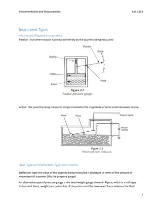
Understanding Electronic Flight Instrument System (EFIS)

An Electronic Flight Instrument System (EFIS) replaces traditional flight deck instruments with electronic displays like the Primary Flight Display (PFD) and Multi-Function Display (MFD). EFIS enhances situational awareness for pilots by consolidating critical flight data in a single, easy-to-read interface. The MFD provides navigational and weather information, while the PFD offers essential flight metrics such as airspeed, altitude, heading, and attitude. EFIS contributes to a more efficient and safer flying experience through advanced alerting systems and customizable display features.

Download Presentation

Please find below an Image/Link to download the presentation.
The content on the website is provided AS IS for your information and personal use only. It may not be sold, licensed, or shared on other websites without obtaining consent from the author. Download presentation by click this link. If you encounter any issues during the download, it is possible that the publisher has removed the file from their server.
E N D
Presentation Transcript
ELECTRONIC FLIGHT INSTRUMENT SYSTEM (EFIS)
An electronic flight instrument system (EFIS) is a flight deck instrument display system that displays flight data electronically rather than electromechanically. An EFIS normally consists of a primary flight display (PFD), multi-function display (MFD), and an engine indicating and crew alerting system (EICAS) display. Early EFIS models used cathode ray tube (CRT) displays, but liquid crystal displays (LCD) are now more common. The complex electromechanical attitude direction indicator (ADI) and horizontal situation indicator (HSI) were the first candidates for replacement by EFIS. Now, however, few flight deck instruments cannot be replaced by an electronic display.
On the flight deck, the display units are the most obvious parts of an EFIS system, and are the features that lead to the term glass cockpit. The display unit that replaces the ADI is called the primary flight display (PFD). If a separate display replaces the HSI, it is called the navigation display. The PFD displays all information critical to flight, including calibrated airspeed, altitude, heading, attitude and vertical speed. The PFD is designed to improve a pilot's situational awareness by integrating this information into a single display instead of six different analog instruments, reducing the amount of time necessary to monitor the instruments. PFDs also increase situational awareness by alerting the aircrew to unusual or potentially hazardous conditions for example, low airspeed, and high rate of descent by changing the color or shape of the display or by providing audio alerts.
However, a simulated ADI is only the centerpiece of the PFD. Additional information is both superimposed on and arranged around this graphic. Another option is to use one large screen to show both the PFD and navigation display. The PFD and navigation display (and multi-function display, where fitted) are often physically identical. The information displayed is determined by the system interfaces where the display units are fitted. Thus, spares holding are simplified: the one display unit can be fitted in any position. LCD units generate less heat than CRTs; an advantage in a congested instrument panel. They are also lighter, and occupy a lower volume.
The MFD (multi-function display) displays navigational and weatherinformation from multiplesystems. MFDs are most frequently designed as "chart-centric", where the aircrew can overlay different information over a maporchart. Examples of MFD overlay information include the aircraft's current route plan, weather information from either on- board radar or lightning detection sensors or ground-based sensors, e.g. restricted airspaceand aircrafttraffic. The MFD can also be used to view other non-overlay type of data (e.g., current route plan) and calculated overlay-type data, e.g., the glide radius of the aircraft, given current location overterrain, winds, and aircraftspeed and altitude. MFDs can also display information about aircraft systems, such as fuel and electrical systems. As with the PFD, the MFD can change the color or shape of the data to alert the aircrew to hazardous situations..
EICAS(Engine Indications and Crew Alerting System) displays information about the aircraft's systems, including its fuel, electrical and propulsion systems (engines). EICAS displays are often designed to mimic traditional round gauges while also supplying digital readouts of the parameters. EICAS improves situational awareness by allowing the aircrew to view complex information in a graphical format and also by alerting the crew to unusual or hazardous situations. For example, if an engine begins to lose oil pressure, the EICAS might sound an alert, switch the display to the page with the oil system information and outline the low oil pressure data with a red box. Unlike traditional round gauges, many levels of warnings and alarms can be set. Proper care must be taken when designing EICAS to ensure that the aircrew are always provided with the most important information and not overloaded with warnings or alarms. ECAM is a similar system used by Airbus, which in addition to providing EICAS functions also recommend remedial action.
EFIS provides pilots with controls that select display range and mode (for example, map) and enter data (such as selected heading). Where other equipment uses pilot inputs, data buses broadcast the pilot's selections so that the pilot need only enter the selection once. For example, the pilot selects the desired level-off altitude on a control unit. The EFIS repeats this selected altitude on the PFD, and by comparing it with the actual altitude (from the air data computer) generates an altitude error display. This same altitude selection is used by the automatic flight control system to level off, and by the altitude alerting system to provide appropriate warnings.
The EFIS visual display is produced by the symbol generator. This receives data inputs from the pilot, signals from sensors, and EFIS format selections made by the pilot. The symbol generator can go by other names, such as display processing computer, display electronics unit, etc. The symbol generator does more than generate symbols. It has (at the least) monitoring facilities, a graphics generator and a display driver. Inputs from sensors and controls arrive via data buses, and are checked for validity. The required computations are performed, and the graphics generator and display driver produce the inputs to the display units.
Like personal computers, flight instrument systems need power-on-self-test facilities and continuous self- monitoring. Flight instrument systems, however, need additional monitoring capabilities: Input validation verify that each sensor is providing valid data Data comparison cross check inputs from duplicated sensors Display monitoring detect failures within the instrument system
With EFIS, the comparator function is simple: Is roll data (bank angle) from sensor 1 the same as roll data from sensor 2? If not, display a warning caption (such as CHECK ROLL) on both PFDs. Comparison monitors give warnings for airspeed, pitch, roll, and altitude indications. More advanced EFIS systems have more comparator monitors.
An EFIS display allows no easy re-transmission of what is shown on the display. What is required is a new approach to display monitoring that provides safety equivalent to that of the traditional system. One solution is to keep the display unit as simple as possible, so that it is less likely to introduce errors. The display unit either works or does not work. A failure is always obvious, never insidious. Now the monitoring function can be shifted upstream to the output of the symbol generator. In this technique, each symbol generator contains two display monitoring channels. One channel, the internal, samples the output from its own symbol generator to the display unit and computes, for example, what roll attitude should produce that indication.
This computed roll attitude is then compared with the roll attitude inputto thesymbol generator. Any difference has probably been introduced by faulty processing, and triggers a warning on the relevantdisplay. The external monitoring channel carries out the same check on the symbol generator on the other side of the flight deck: the Captain's symbol generator checks the First Officer's, the First Officer's checks the Captain's. Whichever symbol generator detects a fault, putsupawarning on itsown display. The external monitoring channel also checks sensor inputs (to thesymbol generator) forreasonableness. A spurious input, such as a radio height greater than the radioaltimeter's maximum, results inawarning.

 is a flight")


 displays navigational")
")