Troubleshooting PCB Control and Configuration
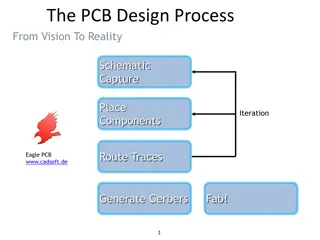
The content discusses issues related to PCB control and configuration, including power-up sequence, component modifications, and mode settings. Recommendations and adjustments are provided for optimal performance. Gerber files are requested for further review of layout discrepancies.

Download Presentation

Please find below an Image/Link to download the presentation.
The content on the website is provided AS IS for your information and personal use only. It may not be sold, licensed, or shared on other websites without obtaining consent from the author.If you encounter any issues during the download, it is possible that the publisher has removed the file from their server.
You are allowed to download the files provided on this website for personal or commercial use, subject to the condition that they are used lawfully. All files are the property of their respective owners.
The content on the website is provided AS IS for your information and personal use only. It may not be sold, licensed, or shared on other websites without obtaining consent from the author.
E N D
Presentation Transcript
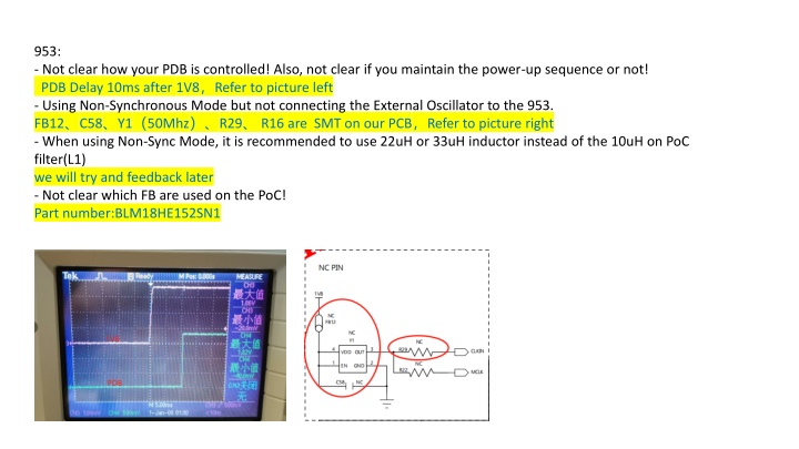
953: - Not clear how your PDB is controlled! Also, not clear if you maintain the power-up sequence or not! PDB Delay 10ms after 1V8 Refer to picture left - Using Non-Synchronous Mode but not connecting the External Oscillator to the 953. FB12 C58 Y1 50Mhz R29 R16 are SMT on our PCB Refer to picture right - When using Non-Sync Mode, it is recommended to use 22uH or 33uH inductor instead of the 10uH on PoC filter(L1) we will try and feedback later - Not clear which FB are used on the PoC! Part number:BLM18HE152SN1
954: - On MODE pin you are using 10K and 12K resistors which is slightly different than our recommendation. If your 1.8V is above than average, then the target voltage will be above our allowed limits. we will change to 10K pulldown (non sync) - On VDD18_CSI a 10uF capacitor is missing. we will try and feedback later - It looks like the FB used on the PoC are not sufficient. These shall have 1.5Kohm impedance! we will change B403 to Part number:BLM18HE152SN,Refer to picture below
Also, from the schematic it looks like the SER is set to Non-Synchronous Mode but not connected to the External Oscillator! At the same time, the DES is setup to run in Sync mode. Please use the same Mode on both devices!! SER is Non-syn Mode,schematic is different with PCB,actaul PCB is Non-syn Mode,FB12 C58 Y1 50Mhz R29 R16 R17 are SMT on our PCB DES is sync mode but our software will change 0x58 BC_FREQ_SELECT to 10Mbps for Non-syn Mode Is this not allowed
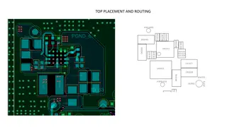
Also, the provide layout screen shot is not sufficient for review. Please provide Gerber files. The one provided in the ppt can't be opened! Please refer to the attachment We want to confirm whether the difference of 100 ohms between those two trace is the same as that of single end 50 ohms . What is your suggestion