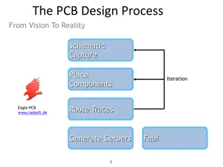
Micromouse PCB Design Guide


Lecture 8
Micromouse PCB
design guide

Components Placement
•
Place library
for
encoder/mot
or to (0,0) to
make it
symmetrical
from left and
right
•
Draw a middle
reference line
•
Use dimension
layer to draw
the outline of
the mouse,
make sure the
length is not
exceed 100mm
to save cost
•
Draw the guide line for the wall and posts in
order to determine the sensor point angles
later
•
Place the
components at
proper position
•
Place sensors at
proper position,
make sure they point
to proper location
•
Make sure the
components won’t
be blocked by motor
mount/encoder
Where should sensors point to?
•
Side sensors point to
somewhere a little to
the front of the post,
when the mouse is at
the center of the cell
•
Front sensors point
outwards about 5-10
degrees, make so it
won’t point to the
side of the wall when
at 1.5 cells away
PCB drawing
Settings
•
No mask for via>12 mills
•
Make 1 mill grid when drawing
and parts placing
Traces
•
MCU pins from
LQFP package are
10-12 mill wide.
•
Try maximum
tracer width for
power/analog
signal related
trace
•
Thinner traces are
OK for digital
signal
Trace thickness
•
Wider trace for
high power
intensive parts, ex.
Vbat Power trace
•
Thinner for signal
traces
•
Polygon may
needed to give
more area for
power trace for
thermo
performance
Trace style
•
good
•
bad
•
Shorter the possible
•
Less turn possible
•
45 degree turns
Small via
•
12 mill via minimum
•
Good for signal trace
•
Better be masked
Large Via
•
Larger via for
power/thermo
intensive
trace/pad/polygon
•
Should not be
masked
•
Drill shouldn’t bee
too big
Polygon
•
First to the First: Don’t make a single GND
polygon for the entire PCB!!!!!
•
Why? Because it will transfer heat to
temperature sensitive components easily from
some heat intensive parts
•
You should place polygon selectively, only on
those parts generate a lot of heat(5V LDO,
motor driver) or the parts are sensitive with
heat(MCU, analog device)
Sample 1
•
Motor driver,
GND polygon,
on both sides
Sample 2
•
Not make the polygon connected
between 5V and MCU since MCU
is temperature sensitive
Distincted Ground
•
MGND
•
DGND
•
AGND
•
Don’t mix them before they reach the
negative terminal of battery
•
AGND is temperature sensitive, make the
trace avoid the hot area if possible
MGND
DGND
AGND
Questions?
This guide provides step-by-step instructions for designing a PCB for a micromouse. It covers components placement, sensor positioning, trace thickness, and trace style to optimize the performance of the micromouse. Proper positioning of components and sensors is crucial, along with considerations for traces width and thickness to ensure efficient power distribution and signal integrity. Follow this guide to create a well-designed PCB for your micromouse project.

Download Presentation

Please find below an Image/Link to download the presentation.
The content on the website is provided AS IS for your information and personal use only. It may not be sold, licensed, or shared on other websites without obtaining consent from the author. Download presentation by click this link. If you encounter any issues during the download, it is possible that the publisher has removed the file from their server.
E N D
Presentation Transcript
Lecture 8 Micromouse PCB design guide
Place library for encoder/mot or to (0,0) to make it symmetrical from left and right Draw a middle reference line
Use dimension layer to draw the outline of the mouse, make sure the length is not exceed 100mm to save cost
Draw the guide line for the wall and posts in order to determine the sensor point angles later
Place the components at proper position Place sensors at proper position, make sure they point to proper location Make sure the components won t be blocked by motor mount/encoder
Where should sensors point to? Side sensors point to somewhere a little to the front of the post, when the mouse is at the center of the cell Front sensors point outwards about 5-10 degrees, make so it won t point to the side of the wall when at 1.5 cells away
Settings No mask for via>12 mills Make 1 mill grid when drawing and parts placing
Traces MCU pins from LQFP package are 10-12 mill wide. Try maximum tracer width for power/analog signal related trace Thinner traces are OK for digital signal
Trace thickness Wider trace for high power intensive parts, ex. Vbat Power trace Thinner for signal traces Polygon may needed to give more area for power trace for thermo performance
Trace style Shorter the possible Less turn possible 45 degree turns good bad
Small via 12 mill via minimum Good for signal trace Better be masked
Large Via Larger via for power/thermo intensive trace/pad/polygon Should not be masked Drill shouldn t bee too big
Polygon First to the First: Don t make a single GND polygon for the entire PCB!!!!! Why? Because it will transfer heat to temperature sensitive components easily from some heat intensive parts You should place polygon selectively, only on those parts generate a lot of heat(5V LDO, motor driver) or the parts are sensitive with heat(MCU, analog device)
Sample 1 Motor driver, GND polygon, on both sides
Not make the polygon connected between 5V and MCU since MCU is temperature sensitive Sample 2
Distincted Ground MGND DGND AGND Don t mix them before they reach the negative terminal of battery AGND is temperature sensitive, make the trace avoid the hot area if possible