System on Chip (SoC) Design and Components
 undefined
SOC
INTRODUCTION


Outline
What is SoC
SoC design
SoC component
SoC working flow
Example
What is SoC
■
System on Chip
■
System?
SoC design
■
Block design
–
Intellectual properties (IP) :
Hard, Soft, Firm
SoC design
■
Platform based design
■
Platform
–
An integrated and managed set of common features
,
upon which a set of products or
product family
can be
built. A platform is a virtual component (VC).
■
Platform-based design
–
An integration oriented design approach emphasizing
systematic reuse
, for developing complex products based
upon platforms and compatible hardware and software
VCs, intended
to reduce development risks, costs, and
time to market
.
Design and Verification Step
30%
70%
Typical SOC design flow
■
Overlap in specification/architecture phase and RTL-design
phase; multiple design changes
–
Architecture design done informally
■
SW development starting late in the project
Top-Down Design Flow
SoC Design Flow
ESL: New SOC Design Flow
■
Architecture closure
–
Achieve a reduction # of RTL iterations
–
Can perform concurrent HW and SW design
–
Shorten the time it takes to get to golden RTL
SoC component
■
CPU
–
OS
■
Bus
–
AHB
–
AXI
■
Peripherals
–
Sensor, Controller, Accelerator
■
IPs
CPU
■
Processors vary in their customization for the problem at hand
Control Unit Sub-Operations
■
Control unit: configures the
datapath operations
–
Sequence of desired
operations (“instructions”)
stored in memory –
“program”
■
Instruction cycle – broken into
several sub-operations, each
one clock cycle, e.g.:
–
Fetch
–
Decode
–
Fetch operands
–
Execute
–
Store results
OS
■
Operating System
■
Manages computer
hardware
and
software
resources
and
provides common services for computer programs
■
RTOS (
R
eal-
T
ime
O
perating
S
ystem)
■
Task scheduling
–
Priority
–
Resource requirements
–
Starting deadline
–
Completion deadline
BUS
■
In a system, various subsystems must have interfaces to one
another
■
The bus serves as a shared communication link between
subsystems
■
Advantages
–
Low cost
–
Versatility
■
Disadvantage
–
Performance bottleneck
AMBA Introduction
■
A
dvanced
M
icrocontroller
B
us
A
rchitecture
■
An on-chip communication standard
■
Three buses defined
–
AHB (Advanced High-performance Bus)
–
ASB (Advanced System Bus)
–
APB (Advanced Peripheral Bus)
AHB
■
AHB master
–
Initiate a read/write operation
–
Only one master is allowed to use the bus
–
uP, DMA, DSP, …
■
AHB slave
–
Respond to a read/write operation
–
Address mapping
–
External memory I/F, APB bridge, internal memory, …
■
AHB arbiter
–
Ensure that which master is active
–
Arbitration algorithm is not defined in ABMA spec.
■
AHB decoder
–
Decode the address and generate select signal to slaves
AHB Bus Interconnection
Basic AHB Transfers 1
■
Address phase
■
Data phase
Basic AHB Transfers 2
■
Multiple transfers
AHB Master Interface
AHB Slave Interface
AHB Arbiter
AHB Decoder
AXI
■
AXI (
A
dvanced e
X
tensible
I
nterface)
■
AXI is burst-based
■
Each transaction has
address and control information
on
address channel that describes the nature of the data to be
transferred
■
Five channels
–
read address channels
–
write address channels
–
read data channel
–
write data channel
–
write response channel
Read Burst
■
Address channel contain address and control information
Overlapping Read Burst
Write Burst
Transaction Ordering
■
Enables
out-of-order
transaction completion
■
Give an
ID tag
to every transaction
–
Transaction with the same ID → in-order
–
Transaction with different ID → can be completed out-of-
order
■
The ID tag is similar to a
master number
, but each master can
implement multiple virtual masters by supplying different ID
tags (virtual master number)
Peripherals
■
Peripherals are often single-purpose processors
–
Performs specific computation task
–
Standard single-purpose processors
■
serial transmission
■
analog/digital conversions
■
I/O peripherals are the communication channels between the
SoC and the real-world
■
The functions of an SoC determines the requirements of
peripherals
Kinds of Peripherals
■
System
–
Timers
–
Counters
–
Watchdog timers
–
Real-time clocks
■
Serial I/F
–
UART
–
I2C
–
I2S
–
SPI
–
FireWire
–
USB
–
Thunderbolt
–
A/D and D/A converters
–
GPIO
■
Functional
–
Image sensor I/F
–
Keypad controllers
–
Pulse width modulators
(PWM)
–
Stepper motor
controllers
–
Communication
peripherals
GPIO
■
GPIO (
G
eneral-
P
urpose
I
nput/
O
utput)
■
Very useful for
–
Debugging
–
Extend the I/O function of the system
–
Can be used for multiple purposes
The Block Diagram of GPIO
I
2
C
■
Inter-IC
■
Two-wire serial bus protocol developed by Philips
Semiconductors nearly 30 years ago
■
Enables peripheral ICs to communicate using simple
communication hardware
SoC working flow
Memory Mapped I/O
■
Each slave occupies a range of (>1KB) address space in the
system
■
All the slaves are addressable
■
Memory mapped register/memory
■
CPU/IP and read/write data to other IP as read/write data
from/to memory
Communication between IPs
■
After the master is granted by the arbiter, it can access all the
slaves on the bus
Communication between CPU
and IP
■
CPU is always the master
■
The IP is always the slave
■
The IP can initiate the
feedback with
interrupt
■
After interrupt, the CPU
enters interrupt mode, and
the interrupt is handled with
interrupt service routine (ISR)
Example: DMA
■
DMA (Direct Memory Access)
Example: DMA
■
Step 0:
CPU check the status of DMA to
make sure it is ready to be used
While(1)
{Read(0x30004, &status)
if(status == 0)
break;
}
Example: DMA
■
Step 1:
CPU sets the (source address),
(destination address and (size)
with the slave I/F
Write(0x30008, 0x10000)
Write(0x3000C, 0x20000)
Write(0x30010, 0x100)
■
Step 2:
starts DMA
Write(0x30000, 0x1)
Example: DMA
■
Step 3:
DMA moves data from memory 1
to memory 2 with the two master
I/F
Example: DMA
■
Step 4:
DMA interrupts CPU
■
Step 5:
CPU checks the status of DMA
Read(0x30004, &status)
Example
■
HDMI Display Controller
Example
CPU
BUS
Interconnect
IP
I
2
C
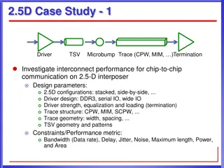
Explore the world of System on Chip (SoC) design, components, and working flow. Learn about Intellectual Properties (IP), platform-based design, typical design flows, top-down design approach, and the emerging Electronic System Level (ESL) design flow. Discover the essential components of an SoC, such as CPU, OS, buses, and peripherals like sensors and accelerators. Delve into the customization of CPU processors and the role of Control Units in managing operations.

Download Presentation

Please find below an Image/Link to download the presentation.
The content on the website is provided AS IS for your information and personal use only. It may not be sold, licensed, or shared on other websites without obtaining consent from the author.If you encounter any issues during the download, it is possible that the publisher has removed the file from their server.
You are allowed to download the files provided on this website for personal or commercial use, subject to the condition that they are used lawfully. All files are the property of their respective owners.
The content on the website is provided AS IS for your information and personal use only. It may not be sold, licensed, or shared on other websites without obtaining consent from the author.
E N D
Presentation Transcript
SOC INTRODUCTION
Outline What is SoC SoC design SoC component SoC working flow Example
What is SoC System on Chip System?
SoC design Block design Intellectual properties (IP) : Hard, Soft, Firm
SoC design Platform based design Platform An integrated and managed set of common features, upon which a set of products or product family can be built. A platform is a virtual component (VC). Platform-based design An integration oriented design approach emphasizing systematic reuse, for developing complex products based upon platforms and compatible hardware and software VCs, intended to reduce development risks, costs, and time to market.
Design and Verification Step 30% 70%
Typical SOC design flow Overlap in specification/architecture phase and RTL-design phase; multiple design changes Architecture design done informally SW development starting late in the project
ESL: New SOC Design Flow Architecture closure Achieve a reduction # of RTL iterations Can perform concurrent HW and SW design Shorten the time it takes to get to golden RTL
SoC component CPU OS Bus AHB AXI Peripherals Sensor, Controller, Accelerator IPs
CPU Processors vary in their customization for the problem at hand
Control Unit Sub-Operations Control unit: configures the datapath operations Sequence of desired operations ( instructions ) stored in memory program Instruction cycle broken into several sub-operations, each one clock cycle, e.g.: Fetch Decode Fetch operands Execute Store results
OS Operating System Manages computer hardware provides common services for computer programs hardware and software software resources resources and RTOS (Real-Time Operating System) Task scheduling Priority Resource requirements Starting deadline Completion deadline
BUS In a system, various subsystems must have interfaces to one another The bus serves as a shared communication link between subsystems Advantages Low cost Versatility Disadvantage Performance bottleneck
AMBA Introduction Advanced Microcontroller Bus Architecture An on-chip communication standard Three buses defined AHB (Advanced High-performance Bus) ASB (Advanced System Bus) APB (Advanced Peripheral Bus)
AHB AHB master Initiate a read/write operation Only one master is allowed to use the bus uP, DMA, DSP, AHB slave Respond to a read/write operation Address mapping External memory I/F, APB bridge, internal memory, AHB arbiter Ensure that which master is active Arbitration algorithm is not defined in ABMA spec. AHB decoder Decode the address and generate select signal to slaves
Basic AHB Transfers 1 Address phase Data phase
Basic AHB Transfers 2 Multiple transfers
AXI AXI (Advanced eXtensible Interface) AXI is burst-based Each transaction has address and control information address and control information on address channel that describes the nature of the data to be transferred Five channels read address channels write address channels read data channel write data channel write response channel
Read Burst Address channel contain address and control information
Transaction Ordering Enables out out- -of of- -order order transaction completion Give an ID tag Transaction with the same ID in-order Transaction with different ID can be completed out-of- order ID tag to every transaction The ID tag is similar to a master number implement multiple virtual masters by supplying different ID tags (virtual master number) master number, but each master can
Peripherals Peripherals are often single-purpose processors Performs specific computation task Standard single-purpose processors serial transmission analog/digital conversions I/O peripherals are the communication channels between the SoC and the real-world The functions of an SoC determines the requirements of peripherals
Kinds of Peripherals System Serial I/F Timers Counters Watchdog timers Real-time clocks Functional Image sensor I/F Keypad controllers Pulse width modulators (PWM) Stepper motor controllers Communication peripherals UART I2C I2S SPI FireWire USB Thunderbolt A/D and D/A converters GPIO
GPIO GPIO (General-Purpose Input/Output) Very useful for Debugging Extend the I/O function of the system Can be used for multiple purposes
I2C Inter-IC Two-wire serial bus protocol developed by Philips Semiconductors nearly 30 years ago Enables peripheral ICs to communicate using simple communication hardware
Memory Mapped I/O Each slave occupies a range of (>1KB) address space in the system All the slaves are addressable Memory mapped register/memory CPU/IP and read/write data to other IP as read/write data from/to memory
Communication between IPs After the master is granted by the arbiter, it can access all the slaves on the bus
Communication between CPU and IP CPU is always the master The IP is always the slave The IP can initiate the feedback with interrupt After interrupt, the CPU enters interrupt mode, and the interrupt is handled with interrupt service routine (ISR)
Example: DMA DMA (Direct Memory Access)
Example: DMA Step 0: CPU check the status of DMA to make sure it is ready to be used While(1) { Read(0x30004, &status) if(status == 0) break; }
Example: DMA Step 1: CPU sets the (source address), (destination address and (size) with the slave I/F Write(0x30008, 0x10000) Write(0x3000C, 0x20000) Write(0x30010, 0x100) Step 2: starts DMA Write(0x30000, 0x1)
Example: DMA Step 3: DMA moves data from memory 1 to memory 2 with the two master I/F
Example: DMA Step 4: DMA interrupts CPU Step 5: CPU checks the status of DMA Read(0x30004, &status)
Example HDMI Display Controller
Example BUS CPU Interconnect I2C IP