NSTX-U Project Overview
The NSTX-U project aims to push the boundaries of total energy input with administrative limits in place. The project involves tasks and device/diagnostic capability requirements for the first year, as well as university collaborations and theoretical research areas. The administrative limit for total energy input into NSTX-U involves various sources and systems to ensure safe operation within set parameters, with planned collaborations, diagnostics, and research efforts in place.
Download Presentation

Please find below an Image/Link to download the presentation.
The content on the website is provided AS IS for your information and personal use only. It may not be sold, licensed, or shared on other websites without obtaining consent from the author.If you encounter any issues during the download, it is possible that the publisher has removed the file from their server.
You are allowed to download the files provided on this website for personal or commercial use, subject to the condition that they are used lawfully. All files are the property of their respective owners.
The content on the website is provided AS IS for your information and personal use only. It may not be sold, licensed, or shared on other websites without obtaining consent from the author.
E N D
Presentation Transcript
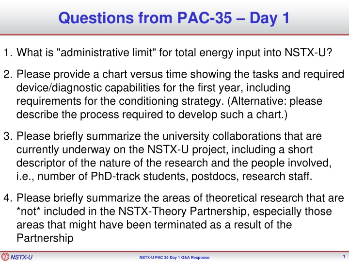
Questions from PAC-35 Day 1 1. What is "administrative limit" for total energy input into NSTX-U? 2. Please provide a chart versus time showing the tasks and required device/diagnostic capabilities for the first year, including requirements for the conditioning strategy. (Alternative: please describe the process required to develop such a chart.) 3. Please briefly summarize the university collaborations that are currently underway on the NSTX-U project, including a short descriptor of the nature of the research and the people involved, i.e., number of PhD-track students, postdocs, research staff. 4. Please briefly summarize the areas of theoretical research that are *not* included in the NSTX-Theory Partnership, especially those areas that might have been terminated as a result of the Partnership NSTX-U 1 NSTX-U PAC 35 Day 1 Q&A Response
Response to Question 1 - Executive Summary (What is "administrative limit" for total energy input into NSTX-U?) Beams have energy limits. For six sources: 80 kV -> 5 sec, 1.7 MW/source, 6 sources -> 51 MJ 95 kV -> 2 sec, 2.5 MW/source, 6 sources -> 30 MJ Limits handled by numerous timing systems at the source control consoles Vessel is ultimately qualified for 70 MJ total (14 MW x 5 seconds). Assumes cooling water flowing on both inner and outer vessel, and that the inner horizontal target is limited to 5 MW/m2. Cooling H20 on casing behind inner horizontal target implemented from Day 0. Beam armor has dual interlocks on the plasma current. Armor designed to take full power without failing Designed for [10.3 MW, 5 sec] or [15 MW, 1 sec] CFCs, ATJ, Poco NSTX achieved: 600 second cycle with 8 MJ, no active vessel cooling NSTX-U will run on 15-20 minute cycle initially Administrative limit on the pulse length in the commissioning phase will easily keep us in the envelope demonstrated on NSTX. Monitor IR camera data and TCs post-shot. We do not have plans to interlock the discharge against TC or IR TV measurements during the first campaign. We have active plans, in many TSGs, to address peak heat flux mitigation. See backup for more details NSTX-U 2 NSTX-U PAC 35 Day 1 Q&A Response
Response to Question #2 - Highest Level Schedule 2014 2015 Aug. Sept Oct Nov Dec. Jan. Feb. Mar. Apr. May June July Aug Sept. Upgrade Construction CD-4 Bake Comm. Research Operations NSTX-U 3 NSTX-U PAC 35 Day 1 Q&A Response
Implementation Schedule for Diagnostics 2014 2015 Aug. Sept Oct Nov Dec. Jan. Feb. Mar. Apr. May June July Aug Sept. Upgrade Construction CD-4 Bake Comm. Research Operations Most Basic Magnetics Plasma TV General In-Vessel Diagnostic Work MPTS Rayleigh/Raman Scattering Neutron Calibrations Envelope of Experiments Grows as Diagnostic Systems BecomeAvailable Complete magnetics for equilibrium reconstruction ( and EFIT!) Fast Mirnovs & mode spectrograms MPTS Neturon Detectors Filter scopes This will allow a good TRANSP run! We can do important experiments! IR TV RWM sensors (locked modes ) Visible, EUV, SXR spectroscopy Toroidal CHERS MSE-CIF Bolometry New Modified Unchanged Many other diagnostics will be commissioned during this phase as well MPTS = Multi-Pulse Thomson Scattering NSTX-U 4 NSTX-U PAC 35 Day 1 Q&A Response
Implementation Schedule for Conditioning/Fuelling Techniques 2014 2015 Aug. Sept Oct Nov Dec. Jan. Feb. Mar. Apr. May June July Aug Sept. Upgrade Construction CD-4 Bake Comm. Research Operations Glow Discharge System Resistive Bake of the CS Hot Helium Bake of the Outer Vessel and C PFCs (+ resistive bake of the CS) Granule Injector for Dedicated XPs FIReTIP realtime interferometry ELM Pacing with 3D fields Boronization (and are starting to work on it now.) Lithium Evaporators for Research + General Conditioning Timing determined by: Physics goals Have we got a good baseline on boronized conditions? can we diagnose/optimize the B->Li transition? Confidence that no vents will be necessary. Technician and engineer resources. Desire to limit the total Li inventory. New Modified Unchanged Stretch Goals Density Feedback Upward Evaporators (more likely FY16 run) Timing of Li introduction ultimately determined by discussions between run coordinator, TSG leaders, engineering, NSTX-U program management. Supersonic gas injection (SGI) commissioning NSTX-U 5 NSTX-U PAC 35 Day 1 Q&A Response
Implementation Schedule for Control Code/Hardware 2014 2015 Aug. Sept Oct Nov Dec. Jan. Feb. Mar. Apr. May June July Aug Sept. Upgrade Construction CD-4 Bake Comm. Research Operations Rectifier Testing DCPS Basic Power Supply Control Basic gas delivery Physics Algorithms (not priority order) N+li control Multiple X-point tracking & SFD control Automated rampdowns Realtime toroidal rotation and MSE Divertor gas injection and MGI IP control Flux-projection shape control Vertical position control HFS and LFS gas delivery rtEFIT Vertical Position control upgrades RWM control & DEFC ISOFLUX shape control Supersonic Gas Injection CHI and HHFW commissioning New Modified Unchanged NSTX-U 6 NSTX-U PAC 35 Day 1 Q&A Response
Implementation Schedule for Control Code/Hardware 2014 2015 Aug. Sept Oct Nov Dec. Jan. Feb. Mar. Apr. May June July Aug Sept. Upgrade Construction CD-4 Bake Comm. Research Operations Rectifier Testing DCPS Basic Power Supply Control Basic gas delivery Physics Algorithms (not priority order) N+li control Multiple X-point tracking & SFD control Automated rampdowns Realtime toroidal rotation and MSE Divertor gas injection and MGI IP control Flux-projection shape control Vertical position control HFS and LFS gas delivery Note on baseline fueling plan: NSTX system had 1/8 OD long fueling tube on the HFS (~600 ms decay time, of discharge) NSTX-U system uses OD tubes (faster pump-out, fuelling over shorter fraction of discharge). Also have large diameter tubes near the shoulders . rtEFIT Vertical Position control upgrades RWM control & DEFC ISOFLUX shape control Supersonic Gas Injection CHI and HHFW commissioning New Modified Unchanged HFS improvement + SGI + new Boronization will be explored in early FY-15 research NSTX-U 7 NSTX-U PAC 35 Day 1 Q&A Response
Response to Question 3 NSTX-U NSTX-U PAC 35 Day 1 Q&A Response
Question 4a: Briefly summarize the areas of theoretical research that might have been terminated as a result of the Partnership Assumption: Enough funds to support the additional 2.5 Theory + 1.0 CPPG Steve Jardin (M3D-C1): less work on Sawtooth studies on DIIID, CMOD, and ASDEX-U M3D-C1 code modifications to include kinetic effects C.S. Chang et al. (XGC0, XGC1): less work on Gyrokinetic impurity transport in SOL and pedestal (development) Gyrokinetic study of L-H transition Elena Belova (CAE/KAW): less work for Tri Alpha (FRC) Edward Startsev (implementing e-m effects in GTS): less work on HEDP Weixing Wang (GTS core transport studies): less work DIII-D core transport Josh Breslau (VDE simulations): stopped working on innovative stellarator coil design Roscoe White (energetic ion transport by *AE modes): less work on density limit disruptions Amitava Bhattacharjee (helped establish Partnership): delayed greatly finishing review paper on sawtooth physics with Ian Chapman and Hyeon Park AB: working with the NSTX team often produces synergisms in which the whole becomes larger than the sum of the parts. NSTX-U NSTX-U PAC 35 Day 1 Q&A Response
Question 4b: What NSTX-related Theory work is being done outside the NSTX-U/Theory Partnership? NTV Physics (NTVTOK, IPECs/POCA): Columbia U., NSTX-U Kinetic stabilization of IWM, RWM: NSTX-U, Columbia Univ. Development of reduced model for fast ion transport: NSTX-U Transport model validation (RLW, TGLF, MMM): NSTX-U, GA, Lehigh U. Core gyrokinetic studies, including momentum transport (GYRO, GTS, GS2, GEM, GKW): NSTX-U, U. Colorado, U. Bayreuth Impurity transport (MIST/STRAHL): Johns Hopkins U. SOL transport physics, including blobs (UEDGE, SOLPS, SOLT): LLNL, Lodestar Pedestal physics (XGC0,1, ELITE, GS2/GYRO, gyrokinetic edge model development): NSTX-U, GA, ORNL, PPPL Theory Materials modeling: U. Tenn, U. Illinois FW & EBW physics (AORSA, TORIC, GENRAY, CQL3D): ORNL, NSTX-U, MIT, CompX CHI/reconnection modeling (NIMROD): LLNL, U. Wisc. NSTX-U NSTX-U PAC 35 Day 1 Q&A Response
Backup for Question 1 NSTX-U 11 NSTX-U PAC 35 Day 1 Q&A Response
Heating System Limitations from the GRD Beam duration is limited by low cycle fatigue on the primary energy ion dump. 5 seconds: 6*1.7 MW =10.2 MW total power from 6 sources 10 3.0 2.5 8 Power [MW] Duration [s] 2.0 6 1.5 4 1.0 2 0.5 0.0 0 60 70 Acceleration Voltage [kV] 80 90 100 110 Note: Upgrades to hypervapotrons, as envisioned for TPX, would eliminate this issue. Limits enforced by source operators (administratively) and numerous timing systems. The HHFW system is assumed to create 4 MW of power for 5 seconds NSTX-U 12 NSTX-U PAC 35 Day 1 Q&A Response
Vessel is Qualified for 70 MJ on a 20 Minute Cycle Vessel power balance assumed 14 MW for 5 s. is 70 MJ NSTXU-CALC-11-01-00 Assumed that DN plasma ~40% of the power ends up on the horizontal targets For an assumed power loading of 5 MW/m2 on average. 1200 s rep rate = 20 min The CS and outer vessel are actively cooled between shots Capability is new on the CS to buffer the coils from the plasma thermal loads We have had this capability on the outer vessel for bake-out. Under these assumptions, the tile surfaces go toward ~1000 C at the end of the pulse, but the vessel/casing are maintained without boiling the water in any location. The vessel system is qualified for 70 MJ NSTX-U 13 NSTX-U PAC 35 Day 1 Q&A Response
However, the Peak Heat Flux May Prove Problematic Limit #1: Thermal stresses in target tiles can exceed ATJ graphite limits. Inner horizontal target tiles qualified for 5 sec operation at Qave=5 MW/m2, QPk=8.0 MW/m2 Limit #2: Desire to avoid tile surface temperatures exceeding Tmax~1200 C. Due to enhanced sublimation. Conservative assumption: lq=0.92IP QPk=Pheatfdivsin(q) 2pRlqfexp -1.6 Qave=0.63QPk Primary solutions: Discharge Parameters Worst-Case Standard DN Divertor fexp=15 & fdiv=0.4 QPk [MW/m2] fexp=60 & fdiv=0.4 or fexp=15 & fdiv=0.1 QPk [MW/m2] 100% NI IP [MA] Pinj [MW] Heating Duration [s] Time to Tmax [s] Time to Tmax [s] 0.75 1.5 2.0 10.2 10.2 10.2 5.0 5.0 5.0 6 12.6 1.4 0.5 Long Pulse 18 28 Highest Power 1.5 2.0 15.6 15.6 1.5 1.5 27 43 0.6 0.25 NSTX-U 14 BP TSG NSTX-U PAC 35 Day 1 Q&A Response
However, the Peak Heat Flux May Prove Problematic Unless it is Mitigated Limit #1: Thermal stresses in target tiles can exceed ATJ graphite limits. Inner horizontal target tiles qualified for 5 sec operation at Qave=5 MW/m2, QPk=8.0 MW/m2 Limit #2: Desire to avoid tile surface temperatures exceeding Tmax~1200 C. Due to enhanced sublimation. Conservative assumption: lq=0.92IP QPk=Pheatfdivsin(q) 2pRlqfexp -1.6 Qave=0.63QPk Broadening the heat channel (fexp) via the snowflake divertor Increasing the fraction of radiated power (decreasing fdiv) Primary solutions: Discharge Parameters Worst-Case Standard DN Divertor fexp=15 & fdiv=0.4 QPk [MW/m2] fexp=60 & fdiv=0.4 or fexp=15 & fdiv=0.1 QPk [MW/m2] 100% NI IP [MA] Pinj [MW] Heating Duration [s] Time to Tmax [s] Time to Tmax [s] 0.75 1.5 2.0 10.2 10.2 10.2 5.0 5.0 5.0 6 12.6 1.4 0.5 1.5 4.5 7 200 22 8.7 Long Pulse 18 28 Highest Power 1.5 2.0 15.6 15.6 1.5 1.5 27 43 0.6 0.25 7 11 9.3 4.0 NSTX-U 15 BP TSG NSTX-U PAC 35 Day 1 Q&A Response
These Observations Motivate the Strong Desire to Mitigate the Peak Heat Flux Collaborations LLNL and PPPL members of the NSTX-U team collaborating on snowflake divertor research on DIII-D. Physics, control, PPPL members of the NSTX-U team active in radiative divertor control at DIII-D. Engineering Analysis Mike Jaworski and I have been working with analysis division to assess the impact of more realistic heat flux profiles on tile thermal stresses. Infrastructure NSTX-U has more divertor coils in order to optimize the divertor geometry. Installing high-throughput divertor gas systems to control the director radiation. Comprehensive system if IR cameras to asses surface temperatures ORNL collaboration. Plans Heat flux mitigation figures prominently in the plans/goals for ASC, Boundary Physics, and Materials/PFC TSGs. NSTX-U 16 NSTX-U PAC 35 Day 1 Q&A Response
Criterion For Heat Flux Limits Calibrate expression for tile surface temperature against engineering models: Tsurf=CQavet1/2 Use Tsurf=1000 C, t=5 s, Qavg=5 MW/m2. Derive C~90 Cm2/MWs1/2 Derive heat flux Q from simple scalings: Qpeak=Pheatfdivsin(q) 2pRlqfexp -1.6 lq=0.92IP NSTX-U 17 NSTX-U PAC 35 Day 1 Q&A Response









![Project Initiation Document for [Insert.Project.name] [Insert.Project.number]](/thumb/226757/project-initiation-document-for-insert-project-name-insert-project-number.jpg)
