Lay Out of the ILC e+ Target Station. A Suggestion.

Lay Out of the ILC e+ Target Station.
A Suggestion.
Peter Sievers-CERN, Kaoru Yokoya-KEK
ECFA LC 2016-Santander
30. May-4. June 2016
1
Contents
•
1. Introduction.
•
2. Lay Out of the Target Unit.
•
3.Handling of the Target Unit.
•
4.Unforeseen Situations and Accidents.
•
5.Comments.
•
6.Conclusion.
2
1. Introduction
•
A target unit is assumed to be located in a horizontal
tunnel.
•
It comprises the target wheel, the flux concentrator (FC)
and the acceleration cavities.
•
The target unit is embedded in side and top shield.
•
This shield protects the tunnel walls and the infrastructure,
like cable trays, along the tunnel from radiation damage,
corrosion and excessive remnant activity.
•
It must allow access along the tunnel for radiation workers,
after appropriate cooldown time and venting of the air.
•
It must protect the environment (Groundwater, the service
tunnel,…).
3
•
The global layout must be compatible with the
maintenance and replacements also of other, not
necessary activated, beam transport
components, like magnets, beam
instrumentation, valves, pumps and other
services.
•
A remotely controled overhead crane is required
to service the target area.
•
This crane will be parked in a radiation free zone.
•
Alternative, heavy duty transport means might be
considered.
4
2. Layout of the Target Unit
•
As a future option, the space for a collimator upstream of
the target wheel and for its supplies must be foreseen.
•
The target unit comprises a remotely controled, upstream
vacuum flange, the wheel in its vacuum tank, the flux
concentrator, integrated in the same tank and the
downstream acceleration cavity.
•
A sweeping magnet is foreseen downstream of the cavity,
to eliminate «wrong» particles in an e-dump.
•
The unit ends again with a remotely controled vacuum
flange.
•
The photon dump further downstream will be considered
separately.
5
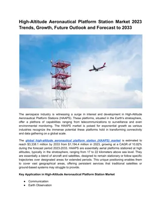
Front View
6
•
The width of the hot central volume is 0.8 m, expected
to be sufficient for the FC and the cavities(tbc).
•
To minimize the width of the hot zone, the vacuum
tank of the wheel with a diameter of 1.2 m cuts locally
into the side shield.
•
The thickness of the side shield is 1. m and that of the
top shield 0.5 m.
•
The overhead crane with a capacity of about 20 t is
used to remove the top and side shield and place it at
convenient area, prior to access the target. The crane
capacity can be reduced to about 10 t by subdividing
further the shielding blocks.
7
•
Sufficient space must be foreseen along the
tunnel to allow the passage and placement of a
transport vehicle with a shielded box. Its width is
about 1.4 m, including lead shields of about
10 cm each ( about 10 µSv/h on the outside).
•
The supplies for the target unit (power and water
for the wheel and the FC, wave guides for the
cavities, instrumentation, interlocks, supplies for
in-situ bake out,…) are guided from the service
tunnel (on the left, not shown) along trenches in
the floor. They are closed by removable covers.
8
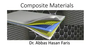
Top View
9
•
The blocks I, II and III of the side shield will be
removed to allow access to the wheel and/or the
whole unit.
•
Safety rules must be respected for emergency
exits of personnel, even when interventions on
the target unit are under way.
•
These have still to be defined and must be
integrated into this scenario.
•
The access procedure to the target zone must be
defined: cool down, clearing the atmosphere,….
10
3. Handling of the Target Unit.
11
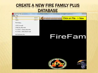
•
1.Remove the blocks I and II by crane into
convenient, temporary storage place.
•
2.Move the Service Vehicle into position.
•
3.Inspect the target. Can the fault be repaired by
local intervention?
•
4.Otherwise, disconnect all supplies.
•
5.Remove the target by crane, place it into the
shielded box and move it into a convenient
storage area.
12
•
6.The reverse procedure is applied for the installation
of a spare target.
•
7.Make a complete, in situ check out (re-alignment(?),
pumping and He-leak test, bake out, checks of
instrumentation, sensors, interlocks, check out all
water circuits, run the wheel and the FC,….).
•
8. Remove the service vehicle and place back the
shielding blocks.
•
9. Check out interlocks and make a dummy run from
the control room.
•
10. Resume operation
13
Robotic Technology in Japan
14
Beamline Geometry
•
EDMS ps-lattice-2012a
•
TDR does not show dimensions of magnets and dumps
•
The components in the first 18m are
–
Flux concentrator (3.2T
0.5T)
–
2x1.27m (11cell, 15MV/m) SW
–
3x4.3m (50cell, 8.5MV/m) TW
–
Both surrounded by 0.5T solenoids
15
4. Unforeseen Situations and
Accidents.
•
This is not a very popular issue, but has to be faced!
•
A few examples:
•
A small water leak in the target zone, not detected in
the circuit, but leading to severe corrosion.
•
The remaining part of the remotely controled vacuum
flange is stuck, corroded or damaged. Need repair or
replacement.
•
Sensors, being part of the interlock chain, should be
accessible for replacement without removing the
whole target.
•
Therefore the possibility to access directly the target,
when in place, is strongly recommended.
16
5. Comments
•
The photon water dump will have a total
length of 3.-5. m. Its operation, maintenance,
handling and exchange has still to be defined.
•
It should be tried to apply a similar procedure
as for the target unit.
•
The production of isotopes and in particular
Tritium, is to be studied.
17
6. Conclusion
•
A scenario is considered, where the handling of
the target takes place inside the target tunnel.
•
This could save heavy civil engineering of
auxiliary handling areas.
•
It requires space in the target tunnel, fitted with
an overhaed crane to manoever the shielding
blocks, and space for the movements of the
service vehicle and the transport vehicle.
•
Convenient means and accessible space for long
term storage of highly activated components
must be foreseen.
18
Thank you for your Attention
•
A last advice:
19
Back Up
20
A detailed layout proposal for the ILC e+ target station, including the target unit structure, maintenance considerations, and safety precautions. The proposal emphasizes remote-controlled systems and shielding for radiation protection.

Download Presentation

Please find below an Image/Link to download the presentation.
The content on the website is provided AS IS for your information and personal use only. It may not be sold, licensed, or shared on other websites without obtaining consent from the author.If you encounter any issues during the download, it is possible that the publisher has removed the file from their server.
You are allowed to download the files provided on this website for personal or commercial use, subject to the condition that they are used lawfully. All files are the property of their respective owners.
The content on the website is provided AS IS for your information and personal use only. It may not be sold, licensed, or shared on other websites without obtaining consent from the author.
E N D
Presentation Transcript
Lay Out of the ILC e+ Target Station. A Suggestion. Peter Sievers-CERN, Kaoru Yokoya-KEK ECFA LC 2016-Santander 30. May-4. June 2016 1
Contents 1. Introduction. 2. Lay Out of the Target Unit. 3.Handling of the Target Unit. 4.Unforeseen Situations and Accidents. 5.Comments. 6.Conclusion. 2
1. Introduction A target unit is assumed to be located in a horizontal tunnel. It comprises the target wheel, the flux concentrator (FC) and the acceleration cavities. The target unit is embedded in side and top shield. This shield protects the tunnel walls and the infrastructure, like cable trays, along the tunnel from radiation damage, corrosion and excessive remnant activity. It must allow access along the tunnel for radiation workers, after appropriate cooldown time and venting of the air. It must protect the environment (Groundwater, the service tunnel, ). 3
The global layout must be compatible with the maintenance and replacements also of other, not necessary activated, beam transport components, like magnets, beam instrumentation, valves, pumps and other services. A remotely controled overhead crane is required to service the target area. This crane will be parked in a radiation free zone. Alternative, heavy duty transport means might be considered. 4
2. Layout of the Target Unit As a future option, the space for a collimator upstream of the target wheel and for its supplies must be foreseen. The target unit comprises a remotely controled, upstream vacuum flange, the wheel in its vacuum tank, the flux concentrator, integrated in the same tank and the downstream acceleration cavity. A sweeping magnet is foreseen downstream of the cavity, to eliminate wrong particles in an e-dump. The unit ends again with a remotely controled vacuum flange. The photon dump further downstream will be considered separately. 5
The width of the hot central volume is 0.8 m, expected to be sufficient for the FC and the cavities(tbc). To minimize the width of the hot zone, the vacuum tank of the wheel with a diameter of 1.2 m cuts locally into the side shield. The thickness of the side shield is 1. m and that of the top shield 0.5 m. The overhead crane with a capacity of about 20 t is used to remove the top and side shield and place it at convenient area, prior to access the target. The crane capacity can be reduced to about 10 t by subdividing further the shielding blocks. 7
Sufficient space must be foreseen along the tunnel to allow the passage and placement of a transport vehicle with a shielded box. Its width is about 1.4 m, including lead shields of about 10 cm each ( about 10 Sv/h on the outside). The supplies for the target unit (power and water for the wheel and the FC, wave guides for the cavities, instrumentation, interlocks, supplies for in-situ bake out, ) are guided from the service tunnel (on the left, not shown) along trenches in the floor. They are closed by removable covers. 8
Top View 9
The blocks I, II and III of the side shield will be removed to allow access to the wheel and/or the whole unit. Safety rules must be respected for emergency exits of personnel, even when interventions on the target unit are under way. These have still to be defined and must be integrated into this scenario. The access procedure to the target zone must be defined: cool down, clearing the atmosphere, . 10
1.Remove the blocks I and II by crane into convenient, temporary storage place. 2.Move the Service Vehicle into position. 3.Inspect the target. Can the fault be repaired by local intervention? 4.Otherwise, disconnect all supplies. 5.Remove the target by crane, place it into the shielded box and move it into a convenient storage area. 12
6.The reverse procedure is applied for the installation of a spare target. 7.Make a complete, in situ check out (re-alignment(?), pumping and He-leak test, bake out, checks of instrumentation, sensors, interlocks, check out all water circuits, run the wheel and the FC, .). 8. Remove the service vehicle and place back the shielding blocks. 9. Check out interlocks and make a dummy run from the control room. 10. Resume operation 13
Beamline Geometry EDMS ps-lattice-2012a TDR does not show dimensions of magnets and dumps The components in the first 18m are Flux concentrator (3.2T 0.5T) 2x1.27m (11cell, 15MV/m) SW 3x4.3m (50cell, 8.5MV/m) TW Both surrounded by 0.5T solenoids 15
4. Unforeseen Situations and Accidents. This is not a very popular issue, but has to be faced! A few examples: A small water leak in the target zone, not detected in the circuit, but leading to severe corrosion. The remaining part of the remotely controled vacuum flange is stuck, corroded or damaged. Need repair or replacement. Sensors, being part of the interlock chain, should be accessible for replacement without removing the whole target. Therefore the possibility to access directly the target, when in place, is strongly recommended. 16
5. Comments The photon water dump will have a total length of 3.-5. m. Its operation, maintenance, handling and exchange has still to be defined. It should be tried to apply a similar procedure as for the target unit. The production of isotopes and in particular Tritium, is to be studied. 17
6. Conclusion A scenario is considered, where the handling of the target takes place inside the target tunnel. This could save heavy civil engineering of auxiliary handling areas. It requires space in the target tunnel, fitted with an overhaed crane to manoever the shielding blocks, and space for the movements of the service vehicle and the transport vehicle. Convenient means and accessible space for long term storage of highly activated components must be foreseen. 18
Thank you for your Attention A last advice: 19
Back Up 20


![[PDF⚡READ❤ONLINE] The International Space Station: Building for the Future (Spri](/thumb/21686/pdf-read-online-the-international-space-station-building-for-the-future-spri.jpg)