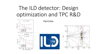
Alignment Scenarios for ILD/ILC Ties Behnke
The calibration and alignment scenarios for ILD/ILC presented at the meeting in Oshu City focus on the initial requirements for tracking, alignment precision, track-based alignment, track samples, vertex detector alignment, and Si tracker alignment techniques. The detailed specifications include lightweight and stiff detectors, stability to electric and magnetic fields, temperature and humidity robustness, and precise alignment for improved momentum resolution. Various alignment methods and tools are discussed to ensure optimal performance and accuracy in the detection systems.
Download Presentation

Please find below an Image/Link to download the presentation.
The content on the website is provided AS IS for your information and personal use only. It may not be sold, licensed, or shared on other websites without obtaining consent from the author.If you encounter any issues during the download, it is possible that the publisher has removed the file from their server.
You are allowed to download the files provided on this website for personal or commercial use, subject to the condition that they are used lawfully. All files are the property of their respective owners.
The content on the website is provided AS IS for your information and personal use only. It may not be sold, licensed, or shared on other websites without obtaining consent from the author.
E N D
Presentation Transcript
Calibration/alignment scenarios for ILD/ILC Ties Behnke based on a talk by Jan Timmermans at the ILD meeting in Oshu City
Initial requirements on tracking Very lightweight, but stiff detectors Stable to electric and magnetic fields (in particular power pulsing effects) Robust against temperature and humidity gradients/variations Precise alignment of (sub)detectors Particular conditions: Push-pull of the two detectors 27.2.2019 ILD meeting KEK 2
Initial and track-based alignment Si tracking sensors positioned inside module 5 m Modules positioned into higher order structures and surveyed/aligned at 100 m Pad positions inside TPC pad plane at <20 m Module positions inside TPC endplate (for current LP) 20 m Track based alignment precision needed: VTX: 2 m Si inner: 4 m, Si outer: 6 m TPC: 20 m This ensures degradation of momentum resolution due to alignement errors w.r.t. nominal of less than 5% 27.2.2019 ILD meeting KEK 3
Track samples Cosmics, but rate limited: Underground Duty cycle 0.5-1 % due to power pulsing Beam collision data: tracks with known momentum from Z, J/ , . Z-peak running @ L = 1032 cm-2s-1: 30k hadronic and 1.5k per 1 pb-1 (takes 3 hours of beam) LEP experience: 10 pb-1 Z running for commissiioning (30 hours of beam) 1 pb-1 per year (depending on interventions ; 0.5 pb-1 per case But could need more e.g. TPC has more (smaller) modules than at LEP. Need for alignment simulation study. 27.2.2019 ILD meeting KEK 4
Vertex Detector Supported by beam pipe, which is supported by the inner support tube During assembly: micron precise pre-alignment via optical survey After installation: beam based alignment Within a layer using overlap between ladders (of few 100 m) Global alignment of layers 27.2.2019 ILD meeting KEK 5
Si tracker Internal hardware alignment of microstrip tracker uses infrared lasers passing through consecutive layers: relative resolution (between measurements) of 10 m within 1 min Deformations/displacements and temperature/humidity monitoring through in-fiber Bragg grating (FBG) sensors, embedded in composite materials ( smart structures ) Frequency Scanning Interferometry under investigation Track-based alignment: Total number of degrees-of-freedom: ~105 For quick re-alignment: if sensor positions within modules known @ 5 m: ndof = ~104-5.104 If only sub-detectors need to be re-aligned: ndof = 26 27.2.2019 ILD meeting KEK 6
TPC calibration issues Need: Good B-field map, 1-2 G precision and sufficient number of points (> 104 locations) Hall probes mounted around TPC; NMR probes? UV lasers: generating ionising tracks in drift volume illuminate the calibration spots on the cathode, which then generate electrons drifting over full length Cosmics: duty cycle 0.5%, would give 10 Hz through hor. cut plane through TPC of 14 m2 at surface; less rate underground Z-peak running: 10 pb-1 commissioning; 0.5-1 pb-1 for quick re- alignment check after incidents (e.g. Push-pull) 27.2.2019 ILD meeting KEK 7
In-situ calibration calorimetry Absolute calibration ECAL can be checked/adjusted by comparison with tracker or using electrons and photons from Bhabha s or return-Z + kinematical constraints. No need for running at Z peak Cosmic rays may not be sufficient for MIP-scale monitoring, but MIP-like segments in hadronic showers can be used Z-peak running: 1 pb-1 sufficient to have >1000 tracks per layer module AHCAL up to layer 20; To reach out to layer 48 would need 20 pb-1, , but can be reduced to 10 pb-1 by adding the mu- pair tracks. 500 GeV: 3% calibration out to layer 20 can be reach with ~2 fb-1 Beam halo muons: could be useful for endcap detectors; rate depends on shielding 27.2.2019 ILD meeting KEK 8
Conclusions Z-peak running: Are the canonical numbers based on LEP experience (10 pb-1 commissioning, 0.5-1 pb-1 quick re-alignment) sufficient for ILD detector modularity? Simulation alignment excercise needed? Alternatives at nominal beam energy? Z return Momentum calibration from Z, J/ , (e.g. Graham Wilson at AWLC14) Cosmics, yes (LHC has shown importance), but: 0.5% duty cycle due to power pulsing reduced rate, because of underground location, but maybe not so deep B-field mapping Can we measure it precisely enough? (study on use of detailed map in reconstruction ongoing) 27.2.2019 ILD meeting KEK 9


