Introduction to Capacitors and Inductors
This chapter covers the basics of capacitors and inductors in electronics, including their properties, uses, and different types. Learn about how capacitors store charge and how inductors store energy in a magnetic field. Explore the world of passive components and their role in electronic circuits.

Download Presentation

Please find below an Image/Link to download the presentation.
The content on the website is provided AS IS for your information and personal use only. It may not be sold, licensed, or shared on other websites without obtaining consent from the author.If you encounter any issues during the download, it is possible that the publisher has removed the file from their server.
You are allowed to download the files provided on this website for personal or commercial use, subject to the condition that they are used lawfully. All files are the property of their respective owners.
The content on the website is provided AS IS for your information and personal use only. It may not be sold, licensed, or shared on other websites without obtaining consent from the author.
E N D
Presentation Transcript
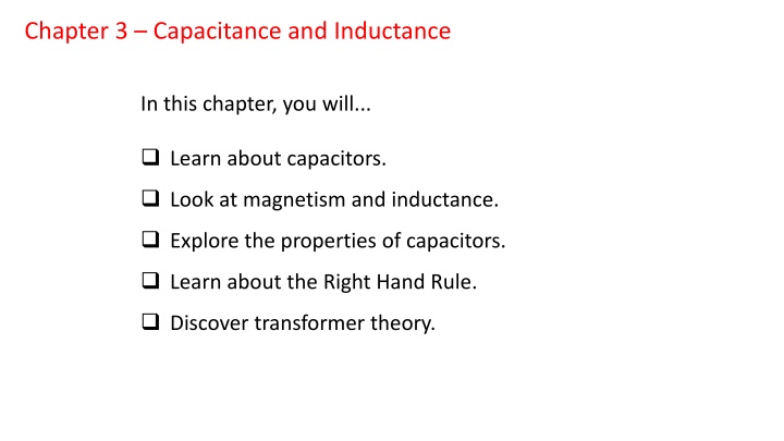
Chapter 3 Capacitance and Inductance In this chapter, you will... Learn about capacitors. Look at magnetism and inductance. Explore the properties of capacitors. Learn about the Right Hand Rule. Discover transformer theory.
You learned about your first passive component in the last chapter: the resistor. Now you will learn about capacitors, inductors, and transformers. A capacitor is a component that can store charge. The amount of charge a capacitor can store is called its capacitance. Inductors are electromagnetic components that can also store energy. But instead of storing charge, they store energy in a magnetic field. Transformers can convert from one AC voltage to another by using an internal magnetic field. These components are used in electronics to smooth waveforms, block DC or AC, to convert from one AC voltage to another, and in filters. A filter is a circuit that removes unwanted frequencies from a signal, or selects a narrow band of signals from a wider spectrum. Your radio tuner works by using a filter.
Chapter 3.1: Introduction to Capacitors A capacitor is a component that can store electric charge. In their simplest possible form, capacitors are nothing more than two conductive plates separated by empty space, air, or some insulating material called a dielectric. If we apply an electric field to the plates with a potential difference, negative charges will build on the negative side, and positive charges will build up on the positive side by charge induction. If we then remove the potential difference, the capacitor will remain in a charged state since the charges on the plates cannot equalize due to the insulating gap. The energy is stored in the electric field between the plates. Let's take a look at Figure 3.1, below.
A capacitor have ability to store charge depends on how close the plates are, the properties of the insulator between the plates, and the surface area of the plates. Bigger plates, closer distances, and better insulators all contribute to higher capacitance. Advances in the material sciences have produced better insulators, making modern capacitors much smaller and more reliable. Capacitors have a unit of measure called the farad. But a farad is quite large, so we use usually use microfarads (abbreviated F.) A microfarad is one millionth of a farad, or 1 10 6 F. Capacitors are commercially available from tens of farads (the so-called supercaps ) down to fractions of a picofarad (as low as 5 10 14 F! ) Capacitors are rated for their working voltage. If a capacitor's working voltage is exceeded, there is risk of failure called dielectric breakdown. Capacitors come in a dizzying array of types and styles. But you will most commonly encounter the capacitors shown in Figure 3.2, above. These are the electrolytic capacitor, tantalum capacitor, polypropylene capacitor, mylar capacitor, and the ceramic disc capacitor.
Aluminum Electrolytic Capacitors Aluminum electrolytic capacitors are made by rolling plates of aluminum foil together with an electrolyte-impregnated tissue to separate the plates. They are typically dark blue (but occasionally other colors) and cylindrical in shape. These capacitors are polarized. That is, they have a negative lead (marked by a stripe) and a positive lead. This has to do with the internal chemistry of the capacitor. Charging these capacitors backwards may result in permanent damage to the capacitor and a face-full of stinky smoke. They range from one microfarad to thousands of microfarads. Because of their leakage and poor tolerance, they are mainly used for power supply filtering and low frequency applications. They are also rated at lower working voltages than other types.
Tantalum Capacitors Tantalum capacitors are very small, but offer increased capacitance for their size. They are much smaller than electrolytic capacitors, making them ideal for use in circuits where size is a factor. Like electrolytic capacitors, they are polarized. And like aluminum electrolytic capacitors, they do not like reverse voltage. In fact, tantalum capacitors have a nickname: bullet caps. They will self-destruct rather spectacularly if inserted into a circuit backwards, often exploding. Therefore, pay attention to the little plus sign on these capacitors, as that tells you which lead is the positive lead. Film Capacitors Polypropylene capacitors, or polycaps, are made using a thin sheet of plastic material as the insulating dielectric. They are usually red and rectangular in shape. They come in ranges from tens of microfarads to fractions of a microfarad. These capacitors have improved tolerance and better characteristics than their mylar cousins
They are non-polarized, and have a wider range of applications due to their better all-around ratings. These capacitors do not vary as much due to temperature and voltage applied, and are a better choice for audio applications. Mylar capacitors can be recognized by their green rectangular packaging. They suffer from dielectric absorption, and do not perform as well as polypropylene capacitors. However, they are cheaper than polypropylene capacitors. They are useful for non-critical applications where cost is a factor. Ceramic Disc Capacitors These capacitors are easy to recognize due to their familiar round shape, flat profile, and their yellow, orange, or red coloring. They are cheap, dependable, and are by far the most commonly used type of capacitor. They offer good performance well into RF (radio frequency) ranges. They typically come in values from picofarads (0.000001 microfarads) up to 0.1 microfarads. These capacitors also have extraordinarily high working voltages, from hundreds to thousands of volts. As such, they can be used for high voltage applications such as voltage multiplier circuits.
Chapter 3.2: Capacitors in Series and Parallel We will start with series-connected capacitors. It seems counter-intuitive, but capacitors do not add up when placed in series as resistors do. Let's look at the equation to gain some insight The equivalent capacitance for series-connected capacitors will be lower than the lowest capacitor's value. Why? Remember that the closer the plates of a capacitor are, the higher the capacitance. By placing capacitors in series, we are increasing the effective plate distance of the equivalent capacitor, thereby reducing the overall capacitance! Our quick trick for resistors in parallel will also work for capacitors in series.
The equivalent capacitance for series-connected capacitors will be lower than the lowest capacitor's value. Why? Remember that the closer the plates of a capacitor are, the higher the capacitance. By placing capacitors in series, we are increasing the effective plate distance of the equivalent capacitor, thereby reducing the overall capacitance! Our quick trick for resistors in parallel will also work for capacitors in series. We now turn our attention to capacitors in parallel. This configuration is so common that it has a special term: capacitor bank. Capacitors in parallel add together (due to the increased effective plate area.) Therefore, computing equivalent capacitance for capacitors in parallel is quite easy.
Power supplies are a common place to find banks of capacitors for filtering DC. Capacitors can discharge very quickly, producing huge current impulses. Therefore, capacitor banks are also used in pulse circuits to achieve very high current, high speed discharges, such as in a rail-gun system.
Chapter 3.3: Capacitor Charge, Discharge, and the RC Time Constant When we charge or discharge capacitors, they do not charge or discharge instantly. They take a certain amount of time to charge or discharge completely. The amount of time to charge a capacitor depends on the capacitance and the resistance in the circuit. Take a look at Figure 3.3, shown below.
When we depress and hold the push-button switch SW1, the capacitor begins charging (the schematic at left.) Instantaneously, the capacitor begins to flood with charges, and looks like a dead short. The only thing limiting current at this point is the resistor. As the charge begins to build up in the capacitor, the current decreases. Finally, after a certain amount of time, the current stops altogether and the capacitor is fully charged. The amount of time it takes to do this depends on the time constant of the capacitor and resistor, called the RC time constant, which we will now define.
The Greek letter (lowercase tau) is used to represent the time constant R * C, and is measured in seconds. After the switch SW1 in Figure 3.3 is pressed and held, the capacitor is said to be fully charged after about 5 , or five tau. If we release switch SW1 at this point, the capacitor will retain the charge until a discharge path is created. We will now give the capacitor charging function for the voltage across a capacitor with respect to time.
When we discharge a capacitor, it begins to dump its stored charge into the discharge path, acting as a temporary voltage source. In Figure 3.4, look at the schematic on the right. If we depress and hold switch SW2, the charge stored in the capacitor is given a discharge path through the resistor. Once again, it takes about 5 to discharge the capacitor to 0 V. We now give the capacitor discharging function for voltage across a capacitor with respect to time
What do you suppose happens to the energy when the capacitor discharges? It is dissipated as heat by the resistor in the discharge path. Therefore, both energy and charge are conserved. Capacitors are said to resist changes in voltage. This is due to their being able to store charges when the applied voltage increases, and to deliver those stored charges when the applied voltage decreases. This is what makes them useful for filtering. They also block DC, since no current flows when fully charged
We just described the functions for charging and discharging capacitors with a series resistance. Let's look at Figure 3.4, shown above. We can clearly see the exponential nature of charge and discharge curves in this graph. After a time of 1 , a charging capacitor is charged to about 63% of the applied voltage, while a discharging capacitor is discharged to about 36% of its initial voltage. We may use these facts to measure an unknown capacitance if the series resistance is known.
Chapter 3.4: Introduction to Inductors An inductor is nothing more than a coil of wire. It might be an air-core inductor, or have a solid core of iron or ferrite. Ferrites are made from a magnetic powder that is pressed into either a cylinder shape or a doughnut shape called a toroid. Inductors use the properties of electricity and certain materials to concentrate a magnetic field. Inductance is measured in henries, represented by a capital H, and come in values from a few microhenries ( H) to tens of henries. Any wire with a current flowing through it generates a magnetic field. This is due to a physical law that states that charges in motion must develop a magnetic field. Therefore, we refer to this phenomenon as electromagnetism, as both electricity and magnetism are intimately linked.
We may understand the relationship between current flow and magnetic fields by using the Right Hand Rule. In Figure 3.5, above, observe the conductor on the left. A current is shown flowing in the upward direction. Now, imagine grasping this conductor with your right hand, with your thumb pointing in the direction of current flow, and observe the curl of your fingers. Your fingers will curl in the direction of the circular magnetic field around the conductor. If we bend a straight conductor into a circle, we have essentially created a one-turn coil. Coils concentrate the circular magnetic field, leading to a north-south polarization. Observe the coil on the right, and pay attention to the circular field lines, with arrows depicting the direction of the field.
When arranged in a coil, the field lines appear to come out of the bottom of the coil, and move toward the top of the coil. If we reverse the direction of current flow in this coil, the direction of the magnetic field will change, leading to a north magnetic pole at the top of the coil, and a south magnetic pole at the bottom of the coil. Computing the inductance of a coil is beyond the scope of this text, and can be rather involved depending on the material used for the core, the number of turns of the coil, the geometric configuration, etc. Even the physical proximity of one coil to another can give rise to mutual inductance, further complicating matters. Therefore, we will place more stress on the uses of inductors rather than going heavily into theory
In Figure 3.5.1, we have some examples of the inductors you will come across. A transformer is also shown, because it is also a device that uses electromagnetism. Transformers transform one voltage to another, and to provide isolation. Transformers are just one example of the many types and styles of inductors you might come across. Let's look at a few of them
RF Inductors Radio frequency (RF) inductors are found in high frequency circuits such as communications equipment. They are typically wound on cardboard, ferrite, or have a wax, plastic, or air core. These have small inductance values, and are used in conjunction with capacitors to make RF filters. These are usually in the millihenry (mH) or microhenry ( H) range. Chokes Chokes are high-current inductors that have a low inductance. They are used for cleaning up AC power lines by chokingoff high frequency signals, and to keep these unwanted signals from being wicked into sensitive electronics. The ferrite core coil and toroid in Figure 3.5.1 are examples of chokes, though some may actually look more like transformers with only one winding. They are typically wound with large diameter magnet wire on powdered ferrite cores. Larger, heavier inductors are used in power conditioning equipment and in heavy industrial applications, and have iron cores.
Transformers Transformers use mutual inductance to convert one AC voltage to another. They are created by winding a coil called the primary winding on a magnetic core, and then winding an electrically isolated coil on top of the first called the secondary winding. As the magnetic field from the primary winding expands, it induces electromotive force in the secondary. That is, the magnetic field lines cut across the secondary, and the moving magnetic field gives rise to current flow in the secondary via magnetic induction. There are many types of transformers. Some tiny transformers are used in high frequency communications circuits (RF transformers.) Larger transformers are used for power supplies, providing safer voltages and isolation from power lines. Some types of transformers do not isolate thesecondary winding and primary, but integrate the two in series. These are called autotransformers.
Chapter 3.5: Inductors in Series and Parallel We will start with series-connected inductors that are not magnetically coupled. As it turns out, inductors add together in series just as resistors do. We will now define the equation for adding inductors in series. For inductors in parallel with no coupling, the equation has the same form as for resistors in parallel.
And, of course, our quick trick for resistors in parallel works for inductors of equal value in parallel.
Chapter 3.6: Inductor Charge, Discharge, and the RL Time Constant Inductors do not store energy in the form of charges like capacitors do. Instead, inductors store energy in the magnetic field that they produce. Even though a capacitor can store charge for a long time, inductors cannot do so. As soon as current is removed, the magnetic field invariably begins to collapse. If there is no path for the discharge, very high kickback voltages can be generated! Inductors resist changes in current (remember that capacitors resist changes in voltage.) Therefore, when the field collapses, a back EMF is generated, as the inductor is trying to continue current flow in the same direction. It is the collapsing magnetic field that generates this back EMF by cutting across the coil as it collapses. So the voltage across the inductor reverses during discharge to keep current flowing in the same direction in the inductor. Let's take a closer look at how this works in Figure 3.5.
Look at the switch in the middle of the schematic, shown above. We are going to make this switch infinitely fast for our discussion. When the switch is flipped over to the voltage source, no current flows at first. The inductor is resisting the sudden increase in current. The inductor appears as an open circuit, and drops all the voltage from the power supply.
As the magnetic field builds in the inductor, current slowly increases until maximum current is achieved. Following the current flow from the power supply, it moves down through the inductor (down the page) and the resistor towards the negative terminal of the power supply. When maximum current is established, the inductor looks like a short circuit and drops no voltage, and the only resistance in the circuit is provided by the resistor. As it turns out, RL circuits have a time constant as well as RC circuits, which is also called tau ( .) It takes about 5 for the current to reach maximum for a series RL circuit. We define the RL time constant below.
We will now give the inductor charging function for inductor current with respect to time, given a seriesresistance R in the current path, as in Figure 3.5. When our infinitely fast switch is flipped to the other position, the inductor suddenly creates a back EMF to resist the reduction of current. It acts as a temporary voltage source of opposite polarity, trying to continue the current flow down the page. It has a discharge path through the resistor, and the
current decays exponentially to zero. Where does the energy from the magnetic field go? It is dissipated by the resistor as heat. Therefore, energy is conserved here, too. Again, the discharge of the inductor takes about 5 . We now give the inductor discharging function for current through an inductor with respect to time, given a series resistor R in the discharge path as in Figure 3.6
In Figure 3.6, we show the charge and discharge curves for inductor current with respect to time. And inductors will reach about 63% of maximum current in one tau when charging.
Chapter 3.7: Basic Transformer Theory Transformer Turns Ratio It was stated earlier in this chapter that transformers use mutual inductance to transform one AC voltage to another. We will now take a closer look at transformers and give some useful hints on how to use them. Let's look at Figure 3.70, shown below Whether transformers step an input AC voltage up or down based the turns ratio of the secondary to the primary windings. On the left side of the diagram above, an AC input waveform is being applied to the primary, shown in red
The magnetic field created by this alternating current is confined to the core, which is represented by the gray square in the diagram. The flux in the core induces current flow in the secondary, shown in blue. We now state a relationship between turns ratio and voltage.
Transformer Power Capacity Transformers are rated according to how much power they can deliver to a load. This is referred to as a transformer's volt-ampere characteristic. Let's say we have a transformer with a VA rating of 100 VA, and a secondary voltage of 10 VAC. Dividing the volt-ampere rating by the primary or secondary operating voltages will yield the maximum current the primary and secondary can handle. Consider a transformer with a VA rating of 100 VA, a primary voltage rating of 100 VAC, and a secondary voltage of 10 VAC. For the secondary the maximum current is, And for the primary, the maximum current is,
Transformer Load Transfer If given the secondary voltage and current (in RMS AC volts and amperes, which we will cover later) we can compute the unknown current in the primary via load transfer. This works because of the law of conservation of energy. If power is being delivered to the load via the secondary winding, then the primary sees this load as an impedance. From the equation, we can calculate for an unknown primary current by solving for it in terms of the known primary voltage, the secondary voltage, and the secondary current
Solving for the primary current transferred via the secondary and load, As long as the load doesn't draw more than the maximum, then the transformer will perform as expected. However, exceeding this maximum current will cause heating in the transformer, possible shorting in the windings, and reduce the life of the transformer


 is used to represent the")