Inductance in Electrical Circuits

 undefined
INDUCTANCE


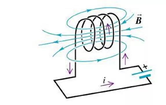
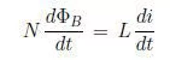
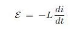
When the current in a loop if wire changes with time, an emf
is induced in the loop according to Faraday’s law. The self-
induced emf is
Ɛ= -L(dI/dt)
Where L is the inductance of the loop. Inductance is
measure of how much opposition a loop offers to a change in
the current in the loop. Inductance has the SI unit of henry
(H), where 1 H= 1 V(s/A)
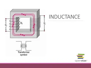
The Inductance of any coil is
L= N
Φ
/I
Where N is the total number of turns and
Φ
is the magnetic
flux through the coil. The inductance of a device depends on
its geometry. For example, the inductance of an air-core
solenoid is
Where l is the length of the solenoid and A is the cross
sectional area.
If a resistor and inductor are connected in series to a
battery of Emf
ε
at time t=0, the current in the circuit
varies in time according to the expression
I=
ε
/R[1-e
t/
τ
]
Where
τ
=L/R is the time constant of the RL circuit. If
we replace the battery in the circuit by a resistance wire,
the current decays exponentially with time according to
the expression
I=
ε
/R[e
t/
τ
]
Where
ε
/R is the initial current in the circuit
The energy stored in the magnetic field of an inductor
carrying a current I is
This energy is the magnetic counterpart to the energy stored
in the electric field of a charged capacitor.
The energy density at a point where the magnetic field is B is
This is used to calculate the energy stored in an inductor
The mutual inductance of a system of two coils is
M
12
=(N
2
Φ
12
)/I
1
= M
21
=(N
1
Φ
21
)/I
2
=M
This mutual inductance allows us to relate the induced emf in
a coil to the changing source current in a nearby coil using
the relationships
ε
2
= - M
12
(dI
1
/dt) and ε
1
= - M
21
(dI
2
/dt)
In an LC circuit that has zero resistance and does not radiate
electromagnetically (an idealization), the values of the charge
on the capacitor and the current in the circuit vary
sinusoidaly in time at an angular frequency given by
ω = 1
/[
√(
LC)]
The energy in an LC circuit continuously transfers between
energy stored in the capacitor and energy stored in the
inductor.
The frequency of an LC circuit is
ƒ = ω
/2π
= 1/2π√(LC)
In a RLC circuit with small resistance, the charge on the
capacitor varies with time according to
Q=Q
max
e
-RT/2L
cos
ω
d
t
where
ω
d
=[ 1/LC – (R/2L)
2
]
1/2
Inductance in electrical circuits is a crucial concept defined by Faraday's law. It measures the opposition to changes in current, with inductors storing energy in their magnetic field. Mutual inductance and LC circuits further showcase the interconnectedness of inductance in electronic systems.

Download Presentation

Please find below an Image/Link to download the presentation.
The content on the website is provided AS IS for your information and personal use only. It may not be sold, licensed, or shared on other websites without obtaining consent from the author.If you encounter any issues during the download, it is possible that the publisher has removed the file from their server.
You are allowed to download the files provided on this website for personal or commercial use, subject to the condition that they are used lawfully. All files are the property of their respective owners.
The content on the website is provided AS IS for your information and personal use only. It may not be sold, licensed, or shared on other websites without obtaining consent from the author.
E N D
Presentation Transcript
When the current in a loop if wire changes with time, an emf is induced in the loop according to Faraday s law. The self- induced emf is = -L(dI/dt) Where L is the inductance of the loop. Inductance is measure of how much opposition a loop offers to a change in the current in the loop. Inductance has the SI unit of henry (H), where 1 H= 1 V(s/A)
The Inductance of any coil is L= N /I Where N is the total number of turns and is the magnetic flux through the coil. The inductance of a device depends on its geometry. For example, the inductance of an air-core solenoid is Where l is the length of the solenoid and A is the cross sectional area.
If a resistor and inductor are connected in series to a battery of Emf at time t=0, the current in the circuit varies in time according to the expression I= /R[1-et/ ] Where =L/R is the time constant of the RL circuit. If we replace the battery in the circuit by a resistance wire, the current decays exponentially with time according to the expression I= /R[et/ ] Where /R is the initial current in the circuit
The energy stored in the magnetic field of an inductor carrying a current I is This energy is the magnetic counterpart to the energy stored in the electric field of a charged capacitor. The energy density at a point where the magnetic field is B is This is used to calculate the energy stored in an inductor
The mutual inductance of a system of two coils is M12=(N2 12)/I1= M21=(N1 21)/I2=M This mutual inductance allows us to relate the induced emf in a coil to the changing source current in a nearby coil using the relationships 2= - M12(dI1/dt) and 1= - M21(dI2/dt)
In an LC circuit that has zero resistance and does not radiate electromagnetically (an idealization), the values of the charge on the capacitor and the current in the circuit vary sinusoidaly in time at an angular frequency given by = 1 /[ (LC)] The energy in an LC circuit continuously transfers between energy stored in the capacitor and energy stored in the inductor. The frequency of an LC circuit is = /2 = 1/2 (LC)
In a RLC circuit with small resistance, the charge on the capacitor varies with time according to Q=Qmaxe-RT/2Lcos dt where d=[ 1/LC (R/2L)2]1/2