INNOVEEA Meeting Highlights at HZB Annual Event
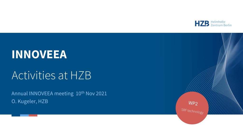


INNOVEEA
Activities at HZB
Annual INNOVEEA meeting 10
th
Nov 2021
O. Kugeler, HZB
WP2
SRF technology


Sustainability goal: Efficient SRF operation in cw mode
Improve
sustainability
of niobium cavities for
2-K operation
●
Eliminate / reduce hazardous HF treatment
●
Reducing the RF surface resistance: e.g. nitrogen infusion
Develop systems for
4-K+ operation
●
conduction cooling of SRF cavities rather than LHe
●
proof-of-principle experiments, on samples
●
proof-of-principle experiments with simple cavity and some RF
●
use of new superconductors … development as part of collaborations,
i.e. EU-ARIES, BMBF-SMART, EU-IFAST, BMBF-NOVALIS (proposed)
●
complimentary to in-house research (QPR)
INNOVEEA
Tasks
1.
Electrodeposition of copper onto Nb
(
talk Alena Prudnikava)
2.
HF free etching of Nb
3.
C
onductive cooling
with
Cu plated Nb
(
joint effort with KIT)
Task 2:
Quadrupole Resonator (QPR)
4
INNOVEEA
Pumping port
Coupler ports
Calorimetry chamber
4 hollow
rods (Nb)
LHe
Cavity (Nb)
Frame
(SS, Ti)
Coaxial gap
Sample
Pole shoes
WP2: HF free etching of Nb
Investigating metallographic polishing in collaboration with CEA to evaluate possibility
of omitting electrochemistry step in the cavity surface preparation recipe.
INNOVEEA
Pictures courtesy Oleksandr Hryhorenko
QPR sample milled
from ASTM0 large
grain material
S
a
= 7 µm
Poor RF performance
Mirror
polishing at
IJCLab
S
a
= 0.5 µm
Great RF performance of baseline sample
(9 Ohm residual resistance at 416 MHz)
After EP 150
µm + annealed
at 900°C under
vacuum + EP 20
µm at CEA
S
a
= 1 µm
Omit this step and re-evaluate performance
Task 3: Beyond the limits of niobium
6
REDUCING THE RF
SURFACE RESISTANCE
S. Keckert, 01.11.2021
Task 3: Conduction cooling of SRF cavities
INNOVEEA
Vacuum (Beam) +RF eigenmode
Nb
3
Sn or other SRF material layer
Nb host cavity (should be avoided if possible)
Cu coating for heat transport
2x thermal
contacts
Transition to cooling media:
•
Braze or weld connection
•
Transition/contact between cooling
media and e.g. pipe/surface
2x thermal
contacts
In worst case 4 thermal contacts/transitions, which
might hinder the heat transport before
reaching steady state
Surface RF losses in SRF Cavities
INNOVEEA
µW/cm²
Parameter:
Maximum field on beam axes 28 MV/m, peak surface magnetic field 60 mT
Superconducting surface resistance 12.3 n
at 1.8 K, total dissipated power 1.1 W
Q
0
=2.2e10
Stored energy in mode 3.05 Joule, but there is more about it…..
TM
010
type of RF
Eigenmode with
axial symmetry in
azimuthal direction:
Main mode applied
in particle accelerators
TM
010
E-field
TM
110
E-field
Power density [µW/cm
2
]
How to cool? Some ideas and basic studies
INNOVEEA
1
st
case:
Only 0.75 mm Cu thick (!) coating and beam tube end flange
cooling to 4.2 K
Losses increase by factor of 3
Thermal runaway?
2
nd
case:
“End-cooling” and additional
Cooling at stiffening ring position,
Cu coating (0.75mm) only between
Cooling rings
T
max
~ 4.3 K
Dissipated average power total surface 4.3 W in all cases
3
rd
case
: “End-cooling” plus some 2 mm diameter Cu connectors
to 4.3 K ring every 45 degree
T
max
~4.5 K
Note: All simulations static, cooling boundaries fixed to 4 K, adiabatic boundaries to all directions, no thermal feedback
of dissipated power vs. surface resistance as a function of temperature, no assumption of thermal contact properties
Equator cooling connectors
might be flexible braids later
Cu coating (0.75 mm)
Good enough for dynamic
response?
T
max
~5.6 K
Thank you.
Acknowledgement
Contributions from:
Oleksandr Hryhorenko, Dmitry Tikhonov, Axel Neumann, Sebastian Keckert
INNOVEEA
Activities at the INNOVEEA meeting on November 10th, 2021 focused on improving sustainability of niobium cavities for 2-K operation, reducing hazardous HF treatments, conducting experiments with new superconductors, investigating metallographic polishing techniques, and addressing RF surface resistance. Collaboration with CEA and other institutions was emphasized to enhance cavity performance and explore new cooling media transitions.

Download Presentation

Please find below an Image/Link to download the presentation.
The content on the website is provided AS IS for your information and personal use only. It may not be sold, licensed, or shared on other websites without obtaining consent from the author.If you encounter any issues during the download, it is possible that the publisher has removed the file from their server.
You are allowed to download the files provided on this website for personal or commercial use, subject to the condition that they are used lawfully. All files are the property of their respective owners.
The content on the website is provided AS IS for your information and personal use only. It may not be sold, licensed, or shared on other websites without obtaining consent from the author.
E N D
Presentation Transcript
INNOVEEA Activities at HZB Annual INNOVEEA meeting 10thNov 2021 O. Kugeler, HZB
INNOVEEA Improve sustainability of niobium cavities for 2-K operation Eliminate / reduce hazardous HF treatment Reducing the RF surface resistance: e.g. nitrogen infusion Develop systems for 4-K+ operation conduction cooling of SRF cavities rather than LHe proof-of-principle experiments, on samples proof-of-principle experiments with simple cavity and some RF use of new superconductors development as part of collaborations, i.e. EU-ARIES, BMBF-SMART, EU-IFAST, BMBF-NOVALIS (proposed) complimentary to in-house research (QPR)
1. Electrodeposition of copper onto Nb (talkAlena Prudnikava) 2. HF free etching of Nb 3. Conductive cooling withCu plated Nb (joint effort withKIT)
INNOVEEA Pumping port Coupler ports LHe Tool at HZB to characteriseRF performanceof flat samples (415, 845, 1285 MHz) Cavity (Nb) Operated in vertical cryostat LHebathat 1.8 K 4 hollow rods (Nb) Coaxial structure thermal decoupling calorimetric measurement ofsurfaceresistance Pole shoes Sample TSample= 1.8 K > 20 K Coaxial gap BSample, max 120 mT (415 MHz) ~ 30 MV/m (TESLA) Frame (SS, Ti) Calorimetry chamber 4
INNOVEEA Investigating metallographic polishing in collaboration with CEA to evaluate possibility of omitting electrochemistry step in the cavity surface preparation recipe. After EP 150 m + annealed at 900 C under vacuum + EP 20 m at CEA Sa = 1 m QPR sample milled from ASTM0 large grain material Sa = 7 m Poor RF performance Mirror polishing at IJCLab Sa = 0.5 m Great RF performance of baseline sample (9 Ohm residual resistance at 416 MHz) Omit this step and re-evaluate performance Pictures courtesy Oleksandr Hryhorenko
REDUCING THE RF SURFACE RESISTANCE ?S ? ??2exp + ?res ?B? New materials: Large sc energy gap , large ?c Control residual resistance ?res Intrinsic contribution? Cooling conditions, trapped flux Prevent early vortex penetration Multilayer structures ?? ? ?? ?? RBCS@ 1.8 K 3 n RBCS@ 4.2 K 763 n Nb 9.25 K 1.5 meV 39 nm 32 nm Nb3Sn NbTiN 18 K 3.4 meV 90 nm 7 nm << 1 n 12 n 17.3 K 2.8 meV 150 -200 nm 5 nm << 1 n 60 n 6 S. Keckert, 01.11.2021
INNOVEEA Transition to cooling media: Braze or weld connection Transition/contact between cooling media and e.g. pipe/surface 2x thermal contacts Cu coating for heat transport Nb host cavity (should be avoided if possible) Nb3Sn or other SRF material layer 2x thermal contacts Vacuum (Beam) +RF eigenmode In worst case 4 thermal contacts/transitions, which might hinder the heat transport before reaching steady state
INNOVEEA TM010 E-field TM010type of RF Eigenmode with axial symmetry in azimuthal direction: Main mode applied in particle accelerators Power density [ W/cm2] TM110 E-field W/cm Parameter: Maximum field on beam axes 28 MV/m, peak surface magnetic field 60 mT Superconducting surface resistance 12.3 n at 1.8 K, total dissipated power 1.1 W Q0=2.2e10 Stored energy in mode 3.05 Joule, but there is more about it ..
INNOVEEA 2ndcase: End-cooling and additional Cooling at stiffening ring position, Cu coating (0.75mm) only between Cooling rings 1stcase: Only 0.75 mm Cu thick (!) coating and beam tube end flange cooling to 4.2 K Tmax~5.6 K Tmax~ 4.3 K Losses increase by factor of 3 Thermal runaway? Dissipated average power total surface 4.3 W in all cases 3rdcase: End-cooling plus some 2 mm diameter Cu connectors to 4.3 K ring every 45 degree Equator cooling connectors might be flexible braids later Cu coating (0.75 mm) Good enough for dynamic response? Tmax~4.5 K Note: All simulations static, cooling boundaries fixed to 4 K, adiabatic boundaries to all directions, no thermal feedback of dissipated power vs. surface resistance as a function of temperature, no assumption of thermal contact properties
INNOVEEA Acknowledgement Contributions from: Oleksandr Hryhorenko, Dmitry Tikhonov, Axel Neumann, Sebastian Keckert