Geodesy, Map Projections and Coordinate Systems
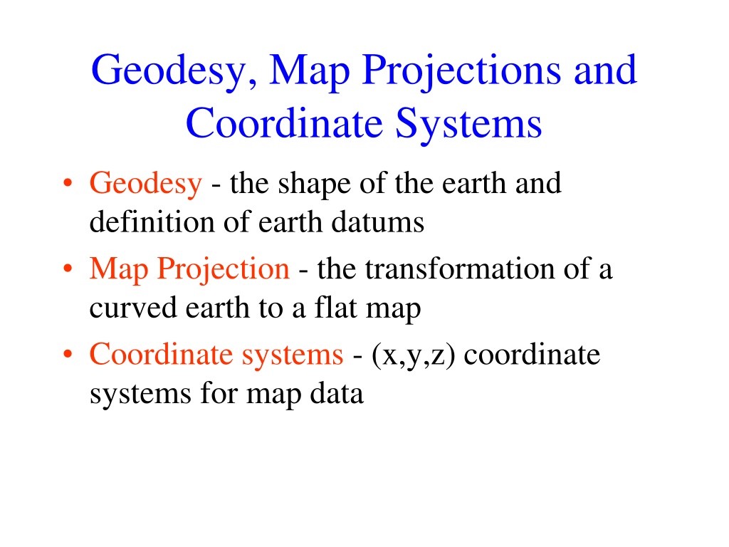

Geodesy, Map Projections and
Coordinate Systems
•
Geodesy
- the shape of the earth and
definition of earth datums
•
Map Projection
- the transformation of a
curved earth to a flat map
•
Coordinate systems
- (x,y,z) coordinate
systems for map data

Learning Objectives:
By the end of this class you should be able to:
•
describe the role of geodesy as a basis for earth datums
•
list the basic types of map projection
•
identify the properties of common map projections
•
properly use the terminology of common coordinate systems
•
use spatial references in ArcMap so that geographic data is
properly displayed
–
determine the spatial reference system associated with a feature class or
data frame
–
use ArcGIS to convert between coordinate systems
•
calculate distances on a spherical earth and in a projected
coordinate system

Readings:
ArcGIS Desktop 9.3 Online Help
Fundamentals of GIS
Map projections and coordinate systemsrojectionsex.cfm?TopicName=An_overview_of_map_phttp://webhelp.esri.com/arcgisdesktop/9.3/index.cfm?TopicName=Three_views_of_GIShttp://webhelp.esri.com/arcgisdesktop/9.3/ind
Spatial Reference = Datum +
Projection +
Coordinate system
•
For consistent analysis the
spatial reference
of
data sets should be the
same.
•
ArcGIS does
projection on the fly
so can display
data with different spatial references properly
if
they are properly specified.
•
ArcGIS terminology
–
Define projection.
Specify the projection for some
data without changing the data.
–
Project.
Change the data from one projection to
another.
Spatial References in action
•
Data frame spatial reference
–
used to display information in ArcMap
–
used to
define the scale
for ArcMap displays including
the legend scale bar
–
inherited from the first layer added
•
Feature class spatial reference
–
underlies the coordinates that define feature locations
–
used in
projection on the fly
to display data using the
data frame spatial reference
•
An example
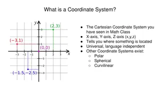
Types of Coordinate Systems
•
(1) Global Cartesian
coordinates (x,y,z) for
the whole earth
•
(2) Geographic
coordinates (
, z)
•
(3) Projected
coordinates (x, y, z) on a local
area of the earth’s surface
•
The z-coordinate in (1) and (3) is defined
geometrically
; in (2) the z-coordinate is
defined
gravitationally
Global Cartesian
Coordinates (x,y,z)
Global Positioning System (GPS)
•
24 satellites
in orbit around the earth
•
Each satellite is continuously
transmitting a
signal
at speed of light, c
•
GPS receiver measures
time lapse,
t
, since
signal left the satellite,
r = c
t
•
Position obtained by intersection of
radial
distances,
r
, from each satellite
•
Differential correction
improves accuracy
Global Positioning using Satellites
r
1
r
3
r
2
r
4
Number
of Satellites
1
2
3
4
Object
Defined
Sphere
Circle
Two Points
Single Point
Geographic Coordinates
(
, z)
•
Latitude (
) and Longitude (
) defined
using an
ellipsoid
, an ellipse rotated about
an axis
•
Elevation (z) defined using
geoid
, a surface
of constant gravitational potential
•
Earth
datums
define standard values of the
ellipsoid and geoid
Shape
of the Earth
We think of the
earth as a
sphere
It is actually a
spheroid
,
slightly larger in radius at
the equator than at the poles
Ellipse
P
F
2
O
F
1
a
b
X
Z
An ellipse is defined by:
Focal length
=
Distance
(F1, P, F2)
is
constant
for all points
on ellipse
When
= 0, ellipse = circle
For the earth:
Major axis, a
= 6378 km
Minor axis, b
= 6357 km
Flattening ratio, f
= (a-b)/a
~ 1/300
Ellipsoid or Spheroid
Rotate an ellipse around an axis
O
X
Z
Y
a
a
b
Rotational axis
Standard Ellipsoids
Ref: Snyder, Map Projections, A working manual, USGS
Professional Paper 1395, p.12
Horizontal Earth Datums
•
An earth datum is defined by an
ellipse
and
an
axis of rotation
•
NAD27
(North American Datum of 1927)
uses the Clarke (1866) ellipsoid on a non
geocentric axis of rotation
•
NAD83
(NAD,1983) uses the GRS80
ellipsoid on a geocentric axis of rotation
•
WGS84
(World Geodetic System of 1984)
uses GRS80, almost the same as NAD83
Definition of Latitude,
(1) Take a point
S
on the surface of the ellipsoid and define
there the
tangent plane
,
mn
(2) Define the line
pq
through S and
normal
to the
tangent plane
(3)
Angle pqr
which this line makes with the equatorial
plane is the latitude
, of point S
O
S
m
n
q
p
r
Cutting Plane of a Meridian
Definition of Longitude,
0°E, W
90°W
(-90 °)
180°E, W
90°E
(+90 °)
-120°
-30°
-60°
-150°
30°
-60°
120°
150°
= the angle between a cutting plane on the prime meridian
and the cutting plane on the meridian through the point, P
P
Latitude and Longitude on a Sphere
Meridian of longitude
Parallel of latitude
X
Y
Z
N
E
W
P
O
R
=0-180°E
=0-90°N
•
Greenwich
meridian
=0
°
•
Equator
=0°
•
•
- Geographic longitude
- Geographic latitude
R - Mean earth radius
O - Geocenter
Length on Meridians and Parallels
0 N
30 N
R
e
R
e
R
R
A
B
C
(Lat, Long) = (
,
)
Length on a Meridian:
AB = R
e
(same for all latitudes)
Length on a Parallel:
CD = R
R
e
Cos
(varies with latitude)
D
Example:
What is the length of a 1º increment along
on a meridian and on a parallel at 30N, 90W?
Radius of the earth = 6370 km.
Solution:
•
A 1º angle has first to be converted to radians
radians = 180 º, so 1º =
/180 = 3.1416/180 = 0.0175 radians
•
For the meridian,
L = R
e
km
•
For the parallel,
L = R
e
Cos
Cos
km
•
Parallels converge as poles are approached
Curved Earth Distance
(from A to B)
S
h
o
r
t
e
s
t
d
i
s
t
a
n
c
e
i
s
a
l
o
n
g
a
“
G
r
e
a
t
C
i
r
c
l
e
”
A
“
G
r
e
a
t
C
i
r
c
l
e
”
i
s
t
h
e
i
n
t
e
r
s
e
c
t
i
o
n
o
f
a
s
p
h
e
r
e
w
i
t
h
a
p
l
a
n
e
g
o
i
n
g
t
h
r
o
u
g
h
i
t
s
c
e
n
t
e
r
.
1
.
S
p
h
e
r
i
c
a
l
c
o
o
r
d
i
n
a
t
e
s
c
o
n
v
e
r
t
e
d
t
o
C
a
r
t
e
s
i
a
n
c
o
o
r
d
i
n
a
t
e
s
.
2
.
V
e
c
t
o
r
d
o
t
p
r
o
d
u
c
t
u
s
e
d
t
o
c
a
l
c
u
l
a
t
e
a
n
g
l
e
f
r
o
m
l
a
t
i
t
u
d
e
a
n
d
l
o
n
g
i
t
u
d
e
3
.
G
r
e
a
t
c
i
r
c
l
e
d
i
s
t
a
n
c
e
i
s
R
,
w
h
e
r
e
R
=
6
3
7
0
k
m
2
Longley et al. (2001)
Example – Distance from Logan to Austin
Representations of the Earth
Mean Sea Level is a surface of constant
gravitational potential
called the
Geoid
Geoid and Ellipsoid
Ocean
Geoid
Earth surface
Ellipsoid
Gravity Anomaly
Gravity anomaly
is the elevation difference between
a standard shape of the earth (ellipsoid) and a surface
of constant gravitational potential (geoid)
Definition of Elevation
Elevation Z
•
P
z = z
p
z = 0
Mean Sea level = Geoid
Land Surface
Elevation is measured from the Geoid
http://www.csr.utexas.edu/ocean/mss.html
Vertical Earth Datums
•
A vertical datum defines elevation, z
•
NGVD29
(National Geodetic Vertical
Datum of 1929)
•
NAVD88
(North American Vertical Datum
of 1988)
•
takes into account a map of gravity
anomalies between the ellipsoid and the
geoid
Converting Vertical Datums
•
Corps program Corpscon (not in ArcInfo)
–
http://crunch.tec.army.mil/software/corpscon/corpscon.html
Point file attributed with the
elevation difference between
NGVD 29 and NAVD 88
NGVD 29 terrain + adjustment
= NAVD 88 terrain elevation
Geodesy and Map Projections
•
Geodesy - the shape of the earth and
definition of earth datums
•
Map Projection - the transformation of a
curved earth to a flat map
•
Coordinate systems - (x,y) coordinate
systems for map data
Earth to Globe to Map
Map Scale:
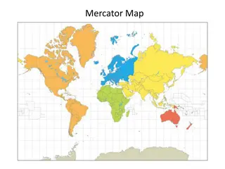
Map Projection:
Scale Factor
Map distance
Globe distance
=
(e.g. 1:24,000)
(e.g. 0.9996)
Geographic and Projected Coordinates
(
)
(x, y)
Map Projection
Types of Projections
•
Conic
(Albers Equal Area, Lambert
Conformal Conic) - good for East-West
land areas
•
Cylindrical
(Transverse Mercator) - good
for North-South land areas
•
Azimuthal
(Lambert Azimuthal Equal Area)
- good for global views
Conic Projections
(Albers, Lambert)
Cylindrical Projections
(Mercator)
Transverse
Oblique
Azimuthal
(Lambert)
Albers Equal Area Conic Projection
Lambert Conformal Conic Projection
Universal Transverse Mercator Projection
Lambert Azimuthal Equal Area Projection
Projections Preserve Some
Earth Properties
•
Area
- correct earth surface area (Albers
Equal Area) important for mass balances
•
Shape
- local angles are shown correctly
(Lambert
Conformal
Conic)
•
Direction
- all directions are shown correctly
relative to the center (Lambert Azimuthal
Equal Area)
•
Distance
- preserved along particular lines
•
Some projections preserve
two
properties
Projection and Datum
Two datasets can differ in both the
projection and the datum, so it is
important to know both for every
dataset.
Geodesy and Map Projections
•
Geodesy - the shape of the earth and
definition of earth datums
•
Map Projection - the transformation of a
curved earth to a flat map
•
Coordinate systems - (x,y) coordinate
systems for map data
Coordinate Systems
•
Universal Transverse Mercator
(UTM) - a
global system developed by the US Military
Services
•
State Plane Coordinate System
- civilian
system for defining legal boundaries
•
Texas Centric Mapping System
- a
statewide coordinate system for Texas
Coordinate System
(
o
,
o
)
(x
o
,y
o
)
X
Y
Origin
A planar coordinate system is defined by a pair
of orthogonal (x,y) axes drawn through an origin
Universal Transverse
Mercator
•
Uses the
Transverse Mercator
projection
•
Each zone has a
Central Meridian
(
o
),
zones are 6° wide, and go from pole to pole
•
60 zones cover the earth from East to West
•
Reference Latitude
(
o
),
is the equator
•
(Xshift, Yshift) = (x
o
,y
o
) = (500000, 0) in
the Northern Hemisphere, units are meters
UTM Zone 14
Equator
-120°
-90 °
-60 °
-102°
-96°
-99°
Origin
6°
State Plane Coordinate System
•
Defined for each
State
in the United States
•
East-West States
(e.g. Texas) use Lambert
Conformal Conic,
North-South States
(e.g.
California) use Transverse Mercator
•
Texas has
five zones
(North, North Central,
Central, South Central, South) to give
accurate representation
•
Greatest accuracy
for local measurements
Texas Centric Mapping System
•
Designed to give
State-wide
coverage of
Texas without gaps
•
Lambert Conformal Conic
projection with
standard parallels 1/6 from the top and 1/6
from bottom of the State
•
Adapted to Albers
equal area projection for
working in hydrology
ArcGIS
Spatial Reference
Frames
•
Defined for a
feature
dataset
in
ArcCatalog
•
XY Coordinate System
–
Projected
–
Geographic
•
Z Coordinate system
•
Tolerance
•
Resolution
•
M Domain
Horizontal Coordinate Systems
•
Geographic
coordinates (decimal
degrees)
•
Projected
coordinates
(length units, ft or
meters)
Vertical Coordinate Systems
•
None
for 2D
data
•
Necessary
for
3D data
Tolerance
•
The default XY tolerance is the
equivalent of 1mm (0.001
meters) in the linear unit of the
data's XY (horizontal)
coordinate system on the earth
surface at the center of the
coordinate system. For
example, if your coordinate
system is recorded in feet, the
default value is 0.003281 feet
(0.03937 inches). If coordinates
are in latitude-longitude, the
default XY tolerance is
0.0000000556 degrees.
Resolution
Domain Extents
Distance
along a line
Vertical
Horizontal
ArcGIS .prj files
Example – Distance from Logan to Austin by projection
Summary Concepts
•
The
spatial reference
of a dataset comprises
datum
,
projection
and
coordinate system.
•
For consistent analysis the
spatial reference
of data sets should be the
same.
•
ArcGIS does
projection on the fly
so can
display data with different spatial references
properly
if they are properly specified.
•
ArcGIS terminology
–
Define projection.
Specify the projection for
some data without changing the data.
–
Project.
Change the data from one projection
to another.
•
Two basic locational systems:
geometric
or
Cartesian (x, y, z) and
geographic
or
gravitational (
, z)
•
Mean sea level surface or geoid is
approximated by an ellipsoid to define an
earth
datum
which gives (
and distance
above geoid gives (z)
Summary Concepts (Cont.)
Summary Concepts (Cont.)
•
To prepare a map, the earth is first reduced
to a
globe
and then
projected
onto a flat
surface
•
Three basic types of map projections: conic,
cylindrical and azimuthal
•
A particular projection is defined by a
datum
, a projection
type
and a set of
projection
parameters
Summary Concepts (Cont.)
•
Standard coordinate systems
use particular
projections over zones of the earth’s surface
•
Types of standard coordinate systems:
UTM, State Plane
, Texas State Mapping
System, Standard Hydrologic Grid
•
Spatial Reference
in ArcGIS 9 requires
projection and map extent
Delve into the world of geodesy, map projections, and coordinate systems, understanding the shape of the earth, various map projection techniques, and the significance of coordinate systems in spatial data analysis. Learn about spatial references in ArcMap, transforming between coordinate systems, and working with spatial references in GIS tools like ArcGIS.

Download Presentation

Please find below an Image/Link to download the presentation.
The content on the website is provided AS IS for your information and personal use only. It may not be sold, licensed, or shared on other websites without obtaining consent from the author.If you encounter any issues during the download, it is possible that the publisher has removed the file from their server.
You are allowed to download the files provided on this website for personal or commercial use, subject to the condition that they are used lawfully. All files are the property of their respective owners.
The content on the website is provided AS IS for your information and personal use only. It may not be sold, licensed, or shared on other websites without obtaining consent from the author.
E N D
Presentation Transcript
Geodesy, Map Projections and Coordinate Systems Geodesy - the shape of the earth and definition of earth datums Map Projection - the transformation of a curved earth to a flat map Coordinate systems - (x,y,z) coordinate systems for map data
Learning Objectives: By the end of this class you should be able to: describe the role of geodesy as a basis for earth datums list the basic types of map projection identify the properties of common map projections properly use the terminology of common coordinate systems use spatial references in ArcMap so that geographic data is properly displayed determine the spatial reference system associated with a feature class or data frame use ArcGIS to convert between coordinate systems calculate distances on a spherical earth and in a projected coordinate system
Readings: ArcGIS Desktop 9.3 Online Help Fundamentals of GIS http://webhelp.esri.com/arcgisdesktop/9.3/ind ex.cfm?TopicName=Three_views_of_GIS Map projections and coordinate systems http://webhelp.esri.com/arcgisdesktop/9.3/ind ex.cfm?TopicName=An_overview_of_map_p rojections
Spatial Reference = Datum + Projection + Coordinate system For consistent analysis the spatial reference of data sets should be the same. ArcGIS does projection on the fly so can display data with different spatial references properly if they are properly specified. ArcGIS terminology Define projection. Specify the projection for some data without changing the data. Project. Change the data from one projection to another.
Spatial References in action Data frame spatial reference used to display information in ArcMap used to define the scale for ArcMap displays including the legend scale bar inherited from the first layer added Feature class spatial reference underlies the coordinates that define feature locations used in projection on the fly to display data using the data frame spatial reference An example
Types of Coordinate Systems (1) Global Cartesian coordinates (x,y,z) for the whole earth (2) Geographic coordinates ( , z) (3) Projected coordinates (x, y, z) on a local area of the earth s surface The z-coordinate in (1) and (3) is defined geometrically; in (2) the z-coordinate is defined gravitationally
Global Cartesian Coordinates (x,y,z) Z Greenwich Meridian O Y X Equator
Global Positioning System (GPS) 24 satellites in orbit around the earth Each satellite is continuously transmitting a signal at speed of light, c GPS receiver measures time lapse, t, since signal left the satellite, r = c t Position obtained by intersection of radial distances, r, from each satellite Differential correction improves accuracy
Global Positioning using Satellites r2 r3 Number of Satellites 1 2 3 4 Object Defined Sphere Circle Two Points Single Point r4 r1
Geographic Coordinates ( , z) Latitude ( ) and Longitude ( ) defined using an ellipsoid, an ellipse rotated about an axis Elevation (z) defined using geoid, a surface of constant gravitational potential Earth datums define standard values of the ellipsoid and geoid
Shape of the Earth It is actually a spheroid, slightly larger in radius at the equator than at the poles We think of the earth as a sphere
Ellipse An ellipse is defined by: Focal length = Distance (F1, P, F2) is constant for all points on ellipse When = 0, ellipse = circle Z b O a X F1 F2 For the earth: Major axis, a = 6378 km Minor axis, b = 6357 km Flattening ratio, f = (a-b)/a ~ 1/300 P
Ellipsoid or Spheroid Rotate an ellipse around an axis Z b a O Y a X Rotational axis
Standard Ellipsoids Ellipsoid Major axis, a (m) Minor axis, b (m) Flattening ratio, f Clarke (1866) 6,378,206 6,356,584 1/294.98 GRS80 6,378,137 6,356,752 1/298.57 Ref: Snyder, Map Projections, A working manual, USGS Professional Paper 1395, p.12
Horizontal Earth Datums An earth datum is defined by an ellipse and an axis of rotation NAD27 (North American Datum of 1927) uses the Clarke (1866) ellipsoid on a non geocentric axis of rotation NAD83 (NAD,1983) uses the GRS80 ellipsoid on a geocentric axis of rotation WGS84 (World Geodetic System of 1984) uses GRS80, almost the same as NAD83
Definition of Latitude, m p S n O q r (1) Take a point S on the surface of the ellipsoid and define there the tangent plane, mn (2) Define the line pq through S and normal to the tangent plane (3) Angle pqr which this line makes with the equatorial plane is the latitude , of point S
Cutting Plane of a Meridian P Prime Meridian Equator Meridian
Definition of Longitude, = the angle between a cutting plane on the prime meridian and the cutting plane on the meridian through the point, P 180 E, W -150 150 -120 120 90 W (-90 ) 90 E (+90 ) P -60 -60 -30 30 0 E, W
Latitude and Longitude on a Sphere Meridian of longitude Z Greenwich meridian =0 N Parallel of latitude P - Geographic longitude - Geographic latitude E W O Y R R - Mean earth radius =0 Equator O - Geocenter X
Length on Meridians and Parallels (Lat, Long) = ( , ) Length on a Meridian: AB = Re (same for all latitudes) R D R C B Re Re Length on a Parallel: CD = R = Re Cos (varies with latitude) A
Example: What is the length of a 1 increment along on a meridian and on a parallel at 30N, 90W? Radius of the earth = 6370 km. Solution: A 1 angle has first to be converted to radians radians = 180 , so 1 = /180 = 3.1416/180 = 0.0175 radians For the meridian, L = Re = = km For the parallel, L = Re Cos Parallels converge as poles are approached = Cos = km
Curved Earth Distance (from A to B) Shortest distance is along a Great Circle Z A Great Circle is the intersection of a sphere with a plane going through its center. B A 1. Spherical coordinates converted to Cartesian coordinates. Y X 2. Vector dot product used to calculate angle from latitude and longitude 3. Great circle distance is R , where R=6370 km2 1 + R cos (sin sin cos cos cos( )) 1 2 1 2 1 2 Longley et al. (2001)
Representations of the Earth Mean Sea Level is a surface of constant gravitational potential called the Geoid Sea surface Ellipsoid Earth surface Geoid
Geoid and Ellipsoid Earth surface Ocean Geoid Gravity Anomaly Gravity anomaly is the elevation difference between a standard shape of the earth (ellipsoid) and a surface of constant gravitational potential (geoid)
Definition of Elevation Elevation Z P z = zp Land Surface z = 0 Mean Sea level = Geoid Elevation is measured from the Geoid
Vertical Earth Datums A vertical datum defines elevation, z NGVD29 (National Geodetic Vertical Datum of 1929) NAVD88 (North American Vertical Datum of 1988) takes into account a map of gravity anomalies between the ellipsoid and the geoid
Converting Vertical Datums Corps program Corpscon (not in ArcInfo) http://crunch.tec.army.mil/software/corpscon/corpscon.html Point file attributed with the elevation difference between NGVD 29 and NAVD 88 NGVD 29 terrain + adjustment = NAVD 88 terrain elevation
Geodesy and Map Projections Geodesy - the shape of the earth and definition of earth datums Map Projection - the transformation of a curved earth to a flat map Coordinate systems - (x,y) coordinate systems for map data
Earth to Globe to Map Map Projection: Map Scale: Scale Factor Representative Fraction Map distance Globe distance Globe distance Earth distance = = (e.g. 0.9996) (e.g. 1:24,000)
Geographic and Projected Coordinates ( ) (x, y) Map Projection
Types of Projections Conic (Albers Equal Area, Lambert Conformal Conic) - good for East-West land areas Cylindrical (Transverse Mercator) - good for North-South land areas Azimuthal (Lambert Azimuthal Equal Area) - good for global views
Conic Projections (Albers, Lambert)
Cylindrical Projections (Mercator) Transverse Oblique
Azimuthal (Lambert)
Projections Preserve Some Earth Properties Area - correct earth surface area (Albers Equal Area) important for mass balances Shape - local angles are shown correctly (Lambert Conformal Conic) Direction - all directions are shown correctly relative to the center (Lambert Azimuthal Equal Area) Distance - preserved along particular lines Some projections preserve two properties
Projection and Datum Two datasets can differ in both the projection and the datum, so it is important to know both for every dataset.
Geodesy and Map Projections Geodesy - the shape of the earth and definition of earth datums Map Projection - the transformation of a curved earth to a flat map Coordinate systems - (x,y) coordinate systems for map data
Coordinate Systems Universal Transverse Mercator (UTM) - a global system developed by the US Military Services State Plane Coordinate System - civilian system for defining legal boundaries Texas Centric Mapping System - a statewide coordinate system for Texas
Coordinate System A planar coordinate system is defined by a pair of orthogonal (x,y) axes drawn through an origin Y X Origin (xo,yo) ( o, o)
Universal Transverse Mercator Uses the Transverse Mercator projection Each zone has a Central Meridian ( o), zones are 6 wide, and go from pole to pole 60 zones cover the earth from East to West Reference Latitude ( o), is the equator (Xshift, Yshift) = (xo,yo) = (500000, 0) in the Northern Hemisphere, units are meters
UTM Zone 14 -99 -102 -96 6 Origin Equator -60 -90 -120
State Plane Coordinate System Defined for each State in the United States East-West States (e.g. Texas) use Lambert Conformal Conic, North-South States (e.g. California) use Transverse Mercator Texas has five zones (North, North Central, Central, South Central, South) to give accurate representation Greatest accuracy for local measurements
Texas Centric Mapping System Designed to give State-wide coverage of Texas without gaps Lambert Conformal Conic projection with standard parallels 1/6 from the top and 1/6 from bottom of the State Adapted to Albers equal area projection for working in hydrology
ArcGIS Spatial Reference Frames Defined for a feature dataset in ArcCatalog XY Coordinate System Projected Geographic Z Coordinate system Tolerance Resolution M Domain


")
")

")