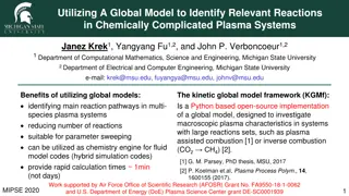
Advanced Plasma Control Systems in Fusion Experiments

The construction of control systems for high-performance plasma with limited actuators or diagnostics is crucial for ongoing fusion experiments like ITER and DEMO. This involves developing control logic, categorizing various parameters, and understanding actuator systems. Multiple control experiments, simulations, and fusion power control scenarios are explored to achieve efficient plasma stability and shape. The need for detailed discussions and considerations of coupling effects in multiple control setups is highlighted throughout the content.

Download Presentation

Please find below an Image/Link to download the presentation.
The content on the website is provided AS IS for your information and personal use only. It may not be sold, licensed, or shared on other websites without obtaining consent from the author.If you encounter any issues during the download, it is possible that the publisher has removed the file from their server.
You are allowed to download the files provided on this website for personal or commercial use, subject to the condition that they are used lawfully. All files are the property of their respective owners.
The content on the website is provided AS IS for your information and personal use only. It may not be sold, licensed, or shared on other websites without obtaining consent from the author.
E N D
Presentation Transcript
Introduction Commercial [2] ITER [1] DEMO [2] Under construction Construction of control system is needed. Construction of control system for high performance plasma with limited actuators or diagnostics is needed.
Control Logic Construction Control parameters Control logic actuators and diagnostics Control System construction
Example of Parameter Categorization Control parameter mid parametermeasurable Item parameter Electrical output ne,Z Ti,Te ,f ,f , D T eff Pfus Safety operation qra ,q ,Zeff ,f eff ,n elm imp edg rad q ,W load div Plasma stability Plasma shape, position , n rotation ,qmin, min N GW Ip,ap ,j(r),Bt p R ,ap, , ,d p p Ip,j(r) gap Detailed discussion is needed.
Example of Actuator Categorization gas-puff pellet NBI RF coil ne Zeff fd,fT,fimp Ti Te qrad qelm Ip j(r) Rp,ap , dgap rotation For multiple control, Coupling effect must be taken into account.
Multiple Control Experiment JT-60 experiment current profile LHCD qmin pressure gradient ITG NBI q-minimum real time control Ti real time control Ti Ref Difference in Ti NBI power q-minimum Ref LHCD power Time [3]T.Suzuki, J.Plasma Fusion Res. Vol86, No9 530-535 (2010) (in Japanese)
1.5D transport code simulation JT-60 experiment current profile LHCD qmin pressure gradient NBI ITG transport code simulation [4] gas-puff Fusion power NBI minimum q-value
Fusion power control simulation Target value Gas-puff [10^19/sec] Fusion power Gas-puff Current profile movie Density profile movie Current profile movie Density profile movie
q-minimum control simulation r/a (q-min) q-min Energy [MW] Current profile Current profile
Simultaneous control simulation Gas-puff [10^19/sec] Energy [MW] r/a (q-min) q-min
Summary of 1.5D simulation Single Control gas-puff Fusion power Easy to control Single Control NBI minimum q-value Simultaneous Control Difficult to control because of their interaction Fusion power gas-puff NBI minimum q-value It is difficult to determine the appropriate gain matrix from only the response characteristics.
Using modern control theory Classical control Modern control 0-D analysis This research Simultaneous control simulation 1.5-D analysis Plasma Experiment JT-60 experiment
Classical and Modern control theory Classical control True system r e u y Black Box Control True system Modern control Model difference r e u y Control Physical Model Managed as disturbance
State space model To determine actuator value, we use this State space model state vector actuator vector Control requirement output vector We can get appropriate actuator value u.
0-D Plasma Physics Model a=2 (m), R=6.2 (m) 0.7
State Equation State vector From Actuator vector we get Output vector x u and
Linearized State Equation ne P control
Adding the Integrator Add the integral term to avoid the disturbance. PI control
2 degree of freedom control Find the equilibrium point from the reference and physical model ueq Feed forward Control u u r e y Feedback Control Plasma Find the feed back gain from physical model
Simulink We use the software MATLAB/Simulink to do simulation. MATLAB/Simulink MATLAB/Simulink
Summary For control logic construction, categorizing of control parameters, actuators and diagnostics is necessarily. In this research, we determine the PI gain from 0-D plasma physics model, and we demonstrate the 0-D control simulation. The simulation using a transport code or plasma control experiment are future work.
Reference [1] http://www.naka.jaea.go.jp/ITER/iter/index.html [2] http://www.asahi-net.or.jp/~rt6k-okn/subject.htm [3] 3]T.Suzuki, J.Plasma Fusion Res. Vol86, No9 530-535 (2010) (in Japanese) [4] Y. Miyoshi et.al PFR Vol.7 2405135 (2012) [5] Control system design (G. C. Goodwin et.al)
The Effect of Disturbance True system Model err r e u y Nominal Model Control d If controller has integrator (1/s), the effect of step disturbance will vanish.
Linearize In this simulation, we assume that equation point = reference point.