Explore the preliminary considerations and new concepts presented in the ILD magnet design projects for superconducting solenoids. Details include manufacturing and assembly plans, site winding options, and transportation logistics. Stay informed about the latest developments in high-strength superconductors.
Please find below an Image/Link to download the presentation.
The content on the website is provided AS IS for your information and personal use only. It may not be sold, licensed, or shared on other websites without obtaining consent from the author. If you encounter any issues during the download, it is possible that the publisher has removed the file from their server.
You are allowed to download the files provided on this website for personal or commercial use, subject to the condition that they are used lawfully. All files are the property of their respective owners.
The content on the website is provided AS IS for your information and personal use only. It may not be sold, licensed, or shared on other websites without obtaining consent from the author.
E N D
Presentation Transcript
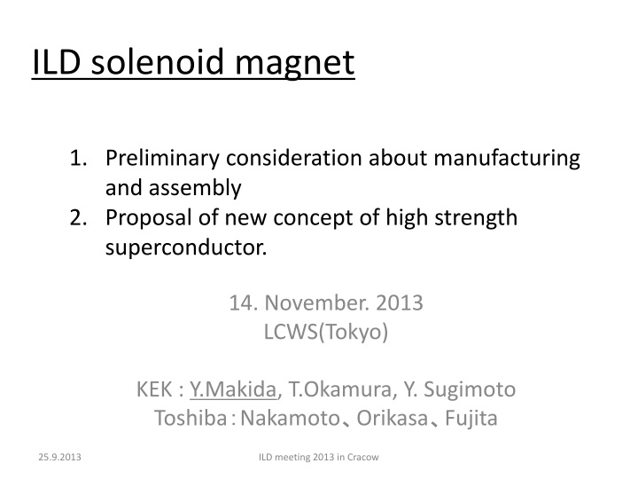
ILD solenoid magnet 1. Preliminary consideration about manufacturing and assembly 2. Proposal of new concept of high strength superconductor. 14. November. 2013 LCWS(Tokyo) KEK : Y.Makida, T.Okamura, Y. Sugimoto Toshiba Nakamoto Orikasa Fujita 25.9.2013 ILD meeting 2013 in Cracow
Introduction We, Makida & Okamura and Sugimoto, discussed how to manufacture ILD solenoid with factory engineers, who have experiences with on-site manufacturing of a large superconducting poloidal magnet set in NIFS (Nat l Ins. Fusion Science). We introduce the meeting minutes. We must start to make a specific plan of manufacturing a ILD solenoid in Japan sites. 14.11.2013 LCwC2013 in Tokyo
ILD magnet design (1) Solenoid Parameter Coil I.D. (mm) 7230 Coil O.D. (mm) 7940 Coil Length(mm) 7350 Cold Mass (ton) 170 Central Field (T) 4 Maximum Field on Cond. (T) 4.6 Nominal Current (kA) 22.4 Inductance (H) 9.2 Stored Energy (GJ) 2.3 E/M (Stored Energy per cold mass)( kJ/kg) 13 14.1.2013 LCWS in Tokyo
ILD magnet design (2) Anti DiD I.D. (mm) 8380 Total Length(mm) 6820 Dipole Field on Beam Axis (T) 0.035 Maximum Field on Cond. (T) 2.0 Nominal Current (kA) 615 Inductance (H) 23 Stored Energy (GJ) 4.4 Anti DiD Parameter (Ver.1) by F. Kircher & B.Parker Outer Vacuum Vessel Thermal Shield Anti-DiD 6880 Cryostat I.D. (mm) Cryostat O.D. (mm) 8800 Solenoid Outer Shell Solenoid Coil Cryostat L (mm) 7810 Thermal Shield Super Insulation Inner Vacuum Vessel 14.1.2013 LCWS in Tokyo
On-site winding or Factory winding? On-site winding Factory winding Lead time It is impossible to complete the manufacture and performance test of the solenoid in 3 years after the completion of the assembly shop. Before the assembly shop become in service, R&D of manufacturing and fabrication of modules can start in the industrial facility. Lead Time of Manufacture 2013 2014 2015 2016 2017 2018 2019 2020 2021 2022 2023 2024 2025 Assembly Shop Construction Experimental Hall Construction Factory Winding Factory Winding R&D of Coil Module Manufacture Module Test Module Assembly Solenoid Performance Test Installation into Hall On On- -site Winding site Winding R&D of Coil Module Manufacture Module Test Module Assembly Solenoid Performance Test Installation into Hall 25.9.2013 ILD meeting 2013 in Cracow
On-site winding or Factory winding? On-site winding Factory winding Transportation of parts or modules There is no problems for transportation of coil parts and conductors. Transportation of single solenoid module of 8 m L2.5 m and single anti-DID of W4.2 m L3.4 m 8.4 m needs special route without obstructions. The modules can be carried in with W3.8 m H9 m. 25.9.2013 ILD meeting 2013 in Cracow
On-site winding or Factory winding? On-site winding Factory winding Manufacturing machine and tools Machining of a 8 m external cylinder needs a large vertical lathe of ten M$. It is possible to use the industrial machines and tools. Of course, a special winding machine should be developed. Manufacturing Cost - Dispatching industrial engineers and technicians for several years. Large machining tools. - Transportation and route improvement. Anyway specific winding machine, curing pot for impregnation etc. must be developed. Factory engineers informed that there is small difference of total cost. 25.9.2013 ILD meeting 2013 in Cracow
Other matters affecting cost & lead time Module number and size In present plan, 3 solenoid modules and 4 poles constituting anti-DID are assembled in the assembly shop. Coil assembly in the factory can become possible by other constitutions , 2 solenoid modules with 4 poles or 4 solenoid modules with 8 poles. Shorter schedule and Lower cost. Field re-calculation is required in the case of 4S and 8DP. More improved route is required in the case of 2S +4DP 25.9.2013 ILD meeting 2013 in Cracow
In the case of ITER D-toroid coil Factory manufactured in Japan, then Transported to Cadarache in France ITER D-toroid coil : 8 m 16 m 3 m, 300 ton Completed coil is put to the marine transportation at the factory without ground transportation in Japan. It is conveyed from a harbor to ITER site in a reserved road. Consideration for issue concerning whether on-site or factory Manufacturing in an industrial facility is preferable. 25.9.2013 ILD meeting 2013 in Cracow
Background of this proposal Current redistribution into low resistive aluminum stabilizer takes the time for second order. From view point of Superconducting Stability : Larger area ratio of cupper matrix in close proximity to NbTi multi filaments is more effective. Accelerator magnets are wound with NbTi/Cu cables. Superconductor Aluminum Stabilizer ?2?(?,?) ??2 ?:?????????? ??????????? ? ?0:???????? ??????????? =?0 ??(?,?) ?? ? From view point of Quench Safety : Large area of Al or Al Alloy give large thermal capacity which prevent the conductor from being burnt out after quench. Initial stage, t = 0 Initial stage, t > 6 sec First, we d like to make simulation study to confirm this proposal. From A. Lee, R.H. Wands and R.W. Fast, Study of current redistribution in an aluminum stabilized superconductor , Cryogenics 1992 Vol 32, No.10, p.865
Cross Sections of Al Stabilized Superconductor in LHC detectors and R&D ILD New Proposal Cu/NbTi Ratio : 2.5 ~3 Rutherford Cable clad with Aluminum Alloy Cu/NbTi Ratio : 1~1.3 From Conceptual Design of the ILD Detector Magnet System by F. Kircher, 11 June 2013
Conductor Proposal Jc : 3000 A/mm2 @ 4.2 K, 5 T Cu ratio : 0.8 Strand D : 1.28 mm No. of Strand : 36 Ic : 67500 A Jc : 3000 A/mm2 @ 4.2 K, 5 T Cu ratio : 2.5 Cu RRR : > 150 Strand D : 1.56 mm No. of Strand : 36 Ic : 67500 A Al+0.1wt%Ni 0.2: ~ 80 MPa Al Alloy 0.2: ~190 (5052) Alloy type should be selected based on metallic bind b/w Cu and Al alloy. From Conceptual Design of the ILD Detector Magnet System by F. Kircher etc. Advantage: Cheaper, Mechanically stronger Disadvantage: Need actual confirmation, Joint resistance R&D Conductor 25.9.2013 ILD meeting 2013 in Cracow
Experimental Study of Al alloy stabilized Conductor Voltage taps to measure power generation and quench propagation Pick up coil to measure current re-distribution Carbon Paste in FRP Tube to ignite normal zone (quench) 5 T MQE (Minimum Quench Energy) >> MQE in Pure Al MQE in Al Alloy Or >= 0.1 A Now, discussion with a Conductor Product about R&D conductor R&D Conductor 14.Nov.2013 LCWS2013 in Tokyo


")
")