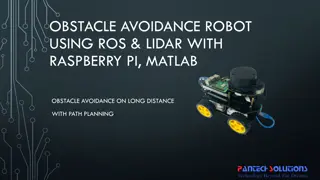
Innovative LiDAR Cave Mapper for Cavers
Develop a portable and cost-effective LiDAR cave mapper to assist freelance cavers in mapping caves efficiently. The project aims to create a device that is affordable, DIY-style, and open-source, making cave mapping more accessible and accurate. The team from FAMU-FSU College of Engineering strives to design a fully rotational system with precise mapping capabilities while keeping the device user-friendly and lightweight. By utilizing LiDAR technology, the project seeks to revolutionize cave mapping processes and overcome the limitations of traditional methods.

Download Presentation

Please find below an Image/Link to download the presentation.
The content on the website is provided AS IS for your information and personal use only. It may not be sold, licensed, or shared on other websites without obtaining consent from the author.If you encounter any issues during the download, it is possible that the publisher has removed the file from their server.
You are allowed to download the files provided on this website for personal or commercial use, subject to the condition that they are used lawfully. All files are the property of their respective owners.
The content on the website is provided AS IS for your information and personal use only. It may not be sold, licensed, or shared on other websites without obtaining consent from the author.
E N D
Presentation Transcript
LIDAR CAVE MAPPER FAMU-FSU College of Engineering ME & ECE Senior Design
Our Team Alisha Hunt Project Manager James Oliveros Lead ECE Spencer Day Lead ME Cesar Rivas Financial Advisor Webmaster Hunter Hayden Power Engineer Jake Ogburn
Table of Contents Problem Description Project Requirements Background Justification Engineering Problems Design
The Problem Cave mapping can be a very expensive undertaking. We need to create a portable cave mapper device for freelance cavers. Current LiDAR devices are expensive and cave mapping is often done using notepads and measuring tape. This project is intended to make LiDAR devices more accessible to cavers by both making it affordable and simple DIY style with open source code. Alisha Hunt
Sample Scanners Cheaper Scanner: RP LiDAR Professional: FARO Focus 3D Up to 180m range 4.5 hour battery life Can cost $20,000 Only 6m range. 4,000 samples/sec. About $500 Figure 2: FARO Focus 3D LiDAR Scanner Figure 1: RP LiDAR Trigonometric Scanner Alisha Hunt
Design Requirements Must be fully rotational in x, y, and z. Map up to 5cm accuracy Convert data into a 3D image No more than 1.5ft tall Total cost within $500 Weighs no more than 5lbs User friendly (easy to use in dark caves) Must be made entirely of nonmagnetic materials Alisha Hunt
Background: Cave Mapping Traditional approach usually requires a team of people and is time intensive LIDAR technologies have facilitated quicker and more accurate cave mapping techniques Very costly ($50,000+) Figure 3: A scientist attempts to map a cave using a traditional method. James Oliveros
Background: LIDAR Remote Sensing Technology LIDAR (Light Imaging, Detection, And Ranging Utilizes ultraviolet, visible, near infrared light, GPS Figure 4: Schematic showing what LiDAR sees James Oliveros
Background: LIDAR LIDAR has applications in many fields (geology, atmospheric research, geodesy etc.) LIDAR has a wide range of materials with high resolution (30 cm resolution or better) Figure 5: 2007 High-Resolution LIDAR image of Marching Bear Mound Group (Iowa Department of natural Resources) James Oliveros
Justification Most explorers and researchers do not have access to sufficient funding to obtain one of the state of the art LIDAR mapping systems. Most cost tens or even hundreds of thousands of dollars. An affordable, accurate mapping system would allow many more teams of researchers to work together to compile data. Figure 6: Leica ScanStation P40 3D Laser Scanner which costs nearly $125,000 Earth s cave system would be mapped at a drastically more rapid pace than it currently is. Hunter Hayden
Justification Our design could be used in emergency situations i.e. after natural disasters, terror attacks Future iterations of our project could be used in the event of catastrophic events to map damaged buildings or piles of rubble which may have lives trapped inside. It would eventually become a common piece of equipment that researchers, explorers, or rescue operators could use in advance of actual human exploration. Figure 7: Example of a robot being tested for an emergency situation. Hunter Hayden
Engineering problems Power Consumption Two power sources: Motors and Electronics Calculations to supply ample power to both systems Batteries must be small enough to be portable Figure 8: Example Battery pack Jake Ogburn
Engineering problems Coding Full rotational movement in the x, y, and z plane Reading in data and storing to memory Exporting data to AutoCAD to create a 3d image of cavern Figure 9: Sample 3D CAD rendering of a cave. Jake Ogburn
Engineering problems The LiDAR systems needs to be able to rotate with 3 degrees of freedom to collect data from every point in space in the cave. Need to minimize the amount of surface area in the cave that data cannot be collected for due to mounting of the device. i.e. if LiDAR is mounted on a platform, it will not be able to collect data at any angle which drops below the platform. Spencer Day
Concept Frame 1 Specifications Field of view: 270 degrees Stepper motors required: 2 Limitations No view of cave floor Function System as a whole rotates on the X-Z plane Lidar System is mounted to a base that rotates on the Y-Z plane Figure 10: Design Concept 1 Spencer Day
Concept Frame 2 Specifications Field of view: 90 degrees Stepper motors required: 2 Function System rotates in X-Y plane Mirror rotates in Y-Z plane while Lidar signal is reflected toward the cave walls Limitations Can t see the cave ceiling or the cave floor Mirror is fragile and will need extra care and maintenance Gathering date through a reflection will lead to error due to vibration and imperfect reflectivity Figure 11: Design Concept 2 Spencer Day
Concept Frame 3 Specifications Field of view: 360 degrees Number of stepper motors: 2 Function Base rotates in the X-Z plane Lidar is mounted to a bearing that rotates 360 degrees in Y-Z plane Limitations Lidar is vulnerable to environmental elements Blind spot directly below the first stepper motor Figure 12: Design Concept 3 Spencer Day
Electrical Components LIDAR LITE 3 Microcontroller (ARDUINO MEGA 2560) 2 x Stepper Motors (vertical and horizontal directions) Figure 13: Garmin LiDAR Lite v3 2 x Stepper Drivers Inertial Measurement Unit (Accelerometer, Magnetometer, Gyroscope) Batteries External Memory for Data storage Status LED s Cesar Rivas Figure 14: Arduino
Software Components Start timer Device will wait short duration before starting scan, giving user plenty of time to exit cave. Stepper motor controls Program will rotate device 0.9 horizontally and 1.8 vertically. Device will rotate 360 vertically for every 0.9 horizontal step, recording the distance at each point. Each point will produce a 3-element vector. Vectors will be saved as array for easy export of data. Error Detection In the event of a stall during scanning, an LED will be turned on to alert the user. Cesar Rivas
Other Components Tripod Tripod mount for device Battery case Protective and portable case for complete device *Materials chosen must be non-magnetic and light-weight. Cesar Rivas
References "About - ILMF." ILMF. N.p., n.d. Web. 11 Oct. 2016. "Caving Projects." Southern Arizona Grotto. N.p., n.d. Web. 10 Oct. 2016. "LIDAR-Lite V3." - SEN-14032. N.p., n.d. Web. 4 Oct. 2016. "Slamtec's RPLIDAR A2 Has a Range of 6 Meters And Can Take Up To 4000 Samples of Laser Ranging per Second ($480)." Into Robotics. N.p., n.d. Web. 4 Oct. 2016. "Underwater Cave (low Poly)." 3D Model :. N.p., n.d. Web. 10 Oct. 2016. "Vermont Center ForGeographic Information." VCGI LiDAR Program. N.p., n.d. Web. 11 Oct. 2016. "What Is LIDAR." US Department of Commerce, National Oceanic and Atmospheric Administration. N.p., n.d. Web. 6 Oct. 2016. England, Emily. "The Effigy Mounds and Mallam | Anthropology | Luther College." The Effigy Mounds and Mallam | Anthropology | Luther College. N.p., n.d. Web. 13 Oct. 2016. Nguyen, Quyen. "Running a Raspberry Pi from 6 AA Batteries." Tutorial Raspberry Pi :. N.p., 1970. Web. 12 Oct. 2016. S. Kish and B. Broedel, "Introduction to Cave Mapping Design Project," 2016. S. Kish, "Mapping of the Wakulla Springs Conduit-Cave System Using LIDAR and Inertial Navigation Sensor System Prototype Modeling, .