Understanding Ultrasonic Inspection (UT) in NDT
Ultrasonic Inspection (UT) is a nondestructive test method using high-frequency sound energy for flaw detection, dimensional measurements, and material characterization. It involves components like pulser/receiver, transducer, display screen, and piezoelectric element. UT equipment includes thickness gauges, flaw detectors, phased-array detectors, and more. The propagation of sound in materials helps in detecting discontinuities like cracks by analyzing reflected signals.

Uploaded on Sep 24, 2024 | 0 Views
Download Presentation

Please find below an Image/Link to download the presentation.
The content on the website is provided AS IS for your information and personal use only. It may not be sold, licensed, or shared on other websites without obtaining consent from the author. Download presentation by click this link. If you encounter any issues during the download, it is possible that the publisher has removed the file from their server.
E N D
Presentation Transcript
Ultrasonic Inspection (UT) Definitions Ultrasonic Testing (UT) - A nondestructive test method that uses high frequency sound energy to conduct examinations and make measurements. Sound - The mechanical vibration of particles in a medium. Pulser/receiver - electronic device that produces high voltage electrical pulses Transducer - converts the electrical pulses to mechanical vibrations (acoustic energy) by a phenomenon known as piezoelectric effect Ultrasonic Wave Frequency occur at a frequency of >20,000 Hz (20 kHz) Humans are incapable of hearing sounds at this frequency Bats emit ultrasonic waves (they listen to the echoes to locate objects)
Ultrasonic Inspection (UT) Uses for UT Flaw detection/ evaluation Dimensional measurements (ex. part thickness) Material characterization UT Inspection System Components Pulser/receiver electronic device that produces high voltage electrical pulses Transducer converts the electrical pulses to mechanical vibrations (acoustic energy) by a phenomenon known as piezoelectric effect
Ultrasonic Inspection (UT) UT Inspection System Components - Continued Display screen monitor that shows an A-scan, B-scan, and/or C-scan presentation of the sound reflection Piezoelectric Element A crystal or polycrystalline material, which, when mechanically deformed, produces electrical charges, and conversely, when intermittently charged, will deform and produce mechanical vibrations
Ultrasonic Inspection (UT) Some examples of UT equipment DM4 thickness gauges (with digital thickness readout) DMS2 thickness gauges (with A-scan presentation) USN 58L Flaw detectors
Ultrasonic Inspection (UT) Some examples of UT equipment Phased-array flaw detector USM Go Flaw Detector
Ultrasonic Inspection (UT) Propagation of Sound Sound energy introduced in the part propagates (travels) through the material in the form of waves A discontinuity, such as a crack, will reflect some of the sound wave back to the transducer Size of reflected signal depends on both the size of the discontinuity and its distance from the sound source Smaller discontinuities and greater distances result in smaller signals Larger discontinuities and nearer distances result in larger signals
Ultrasonic Inspection (UT) Some Advantages of UT Only single-sided part access is required (with pulse-echo technique) Results are instantaneous Highly accurate in locating flaws and assessing flaw size and shape Depth of penetration superior to other NDT methods
Ultrasonic Inspection (UT) Some Disadvantages of UT Requires more highly skilled operators than some other methods (leads to higher cost) Requires a coupling medium Difficult to inspect materials that are rough, irregular in shape, or nonhomogeneous Cast iron and coarse-grained materials difficult to inspect due to low sound transmission and high signal noise Reference standards are required for equipment calibration and characterization of discontinuities
Ultrasonic Inspection (UT) Brief History of UT Development of sonar technique of sending sound waves through water and observing returning echoes to locate submerged objects Early 1940s Dr. F.A. Firestone developed first pulse-echo instrument to detect deep-seated flaws 1950s Japan used ultrasound to detect gallstones and tumors; later expanded to moving objects such as blood moving through the circulatory system U.S. produced the earliest contact scanner for clinical use
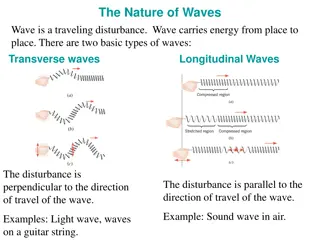
Ultrasonic Inspection (UT) Wave Propagation All materials composed of atoms Sound travels through solids in four principle wave modes Longitudinal waves Shear waves Surface waves Plate waves
Ultrasonic Inspection (UT) Longitudinal and Shear Waves Longitudinal waves also called compression or pressure waves Oscillate in direction of wave propagation as in the movement of a spring Can travel in both liquids and solids Shear waves also called transverse waves Oscillate perpendicular to the direction of wave propagation as in the movement of a wave along a rope Can only travel in solids
Ultrasonic Inspection (UT) Longitudinal Vs. Shear Waves Comparison of Longitudinal and Shear Waves Compression Rarefaction Longitudinal Waves Crest Wavelength Amplitude Trough Shear Waves
Ultrasonic Inspection (UT) Surface Waves and Plate Waves Surface waves also called Rayleigh waves Combine the motion of both longitudinal and shear waves Follow the surface around curves and therefore are sensitive to surface defects Travel at a depth of approximately one wavelength Plate waves also called Lamb waves Similar to surface waves Used for inspection of thin plates (only a few wavelengths in thickness)
Ultrasonic Inspection (UT) Properties of Waves (wavelength, frequency, and velocity) Wavelength Wavelength ( ) the distance in the direction of propagation of a wave for the wave to complete one cycle example, the distance from trough to trough or crest to crest Frequency Frequency (f) the number of complete cycles of a wave passing a given point in a unit time 1 cycle/second = 1 Hz 106 cycles/second = 1 MHz *In UT, frequency is dependent on the frequency rating of the transducer (usually specified in kHz or MHz)
Ultrasonic Inspection (UT) Properties of Waves (continued) Velocity Velocity (v) the speed at which sound waves travel through a medium Typically given in cm/microsecond *Is a function of the material being tested Relationship Between Wave Properties: =v/f Wavelength is directly proportional to the velocity of sound in the material and inversely proportional to the frequency of the sound wave *Rule of Thumb: A discontinuity must be >1/2 the wavelength to be detected (influences transducer frequency selected)
Ultrasonic Inspection (UT) Example Problem #1 You are given the longitudinal velocity in aluminum is 0.25 in/ s (0.65 cm/ s). Using a 2.25 MHz transducer, what is the wavelength of sound produced in the material? Problem #1 Solution =? ? = 0.25 ??/???? 2.25 106 ??????/??? 106 ???? ??? = 0.111 in/cycle Using the rule of thumb, a 2.25 MHz transducer can be used to detect flaws of greater than 0.0556 (0.141 cm) in aluminum.
Ultrasonic Inspection (UT) Example Problem #2 Given a 1 MHz transducer, find the wavelength (?) of a transverse sound wave in carbon steel. Vst,t =0.13 in/ sec. 106 ???? ??? ? ? = 0.13 ??/???? 1.00 106 ??????/??? = = 0.13 in/cycle
Ultrasonic Inspection (UT) Sensitivity The ability of a system (or method) to detect small discontinuities Increases with higher frequencies and shorter wavelengths Resolution Resolution (resolving power) the measure of the capability of a system to separate two discontinuities that are close together in the part of near the part surface * As with sensitivity, resolution increases with an increase in frequency and decrease in wavelength
Ultrasonic Inspection (UT) More on Velocity Dependent on both the density of the material and its elastic properties Also dependent on the type of sound wave Longitudinal waves travel at twice the speed of shear waves Surface waves travel at 90% the speed of shear waves
Ultrasonic Inspection (UT) Attenuation The loss in acoustic energy which occurs between any two points of travel Primarily due to scattering and absorption Scatter dispersion of ultrasonic waves Absorption conversion of sound waves into another energy form (heat) Higher frequency produce more scatter so penetrating power is reduced (depth of penetration of the sound into the material)
Ultrasonic Inspection (UT) Acoustic Impedance of a Material (Z) The factor which controls the propagation of an ultrasonic wave at a boundary interface (its transmission and reflection) Z= *v (where =density and v=velocity) An important factor in the calculation of acoustic transmission and reflection at the boundary of two different materials UT waves are reflected at boundaries where there is a difference in acoustic impedance (difference called impedance mismatch ) The greater the mismatch the greater the sound reflection (and therefore less penetration)
Ultrasonic Inspection (UT) Reflection Vs. Transmission Reflection coefficient, R fraction of wave reflected Transmission coefficient, T- Fraction of wave transmitted on through the part (?2 ?1)2 (?2+?1)2 ? = ? + ? = 1
Ultrasonic Inspection (UT) Acoustic Impedance Data Depends on type of material as well as type of wave (longitudinal vs. shear wave) Example impedance values: Impedance (Z) g/(cm2-sec)*105 Material Water 1.48 Air 0.0004 Aluminum Stainless Steel 17 45.4
Ultrasonic Inspection (UT) Reflection Calculation How much sound is reflected at the interface between water and stainless steel? Solution: from previous table Zwater = 1.48 g/(cm2-sec)*105 Zstainless steel = 45.4 g/(cm2-sec)*105 (1.48 45.4)2 (1.48+45.4)2= 0.878 Which means that 87.8% of the sound is reflected. ? =
Ultrasonic Inspection (UT) Transmission Calculation How much sound is transmitted at the interface between air and aluminum? Solution: from previous table Zair = 0.0004 g/(cm2- sec)*105 and Zaluminum = 17 g/(cm2-sec)*105 ? = (0.0004 +17)2= 0.9999Which means that 99.99% of the sound is reflected. ? + ? = 1 ? = 1 ? = 1 0.9999 = 0.0001 Which means that 0.01% of the sound is transmitted through the part This is why a coupling medium is required at the interface between the transducer and the part. (0.0004 17)2
Ultrasonic Inspection (UT) Snell s Law Describes the relationship between the angle and velocity of the waves. =sin ?2 ??2 where VL1 = longitudinal velocity in material 1 VL2 = longitudinal wave velocity in material 2, 1 = angle of incidence (angle at which the sound penetrates the material), 2 = angle of refraction sin ?1 ??1
Ultrasonic Inspection (UT) Refraction Refraction is the bending of the wave at the material interface If the angle of incidence is 0 (perpendicular to the material) there is no refraction
Ultrasonic Inspection (UT) Mode Conversion Definition: Change from one wave form to another, for example from a longitudinal wave to a shear wave. Occurs when a longitudinal wave hits an interface at an angle to surface (not perpendicular) a shear wave is formed When the angle of refraction of the longitudinal wave becomes 90 degrees, the angle of incidence is called the 1st critical angle All energy form the reflected longitudinal wave converted into a surface-following longitudinal wave (called a creep wave) Only a shear wave now propagates into the material
Ultrasonic Inspection (UT) Mode Conversion (continued) When the angle of refraction of the shear wave becomes 90 degrees, the angle of incidence is called the 2nd critical angle All wave energy is converted into a surface-following shear wave (called a shear creep wave) At an angle of incidence > 2nd critical angle, surface waves are generated
Ultrasonic Inspection (UT) Transducers Active element of most acoustic transducers used today is a piezoelectric ceramic sometimes referred to as a crystal (quartz crystals were originally used as transducers) Lead zirconate titanate most common transducer material Thickness of active element determines the transducer frequency Thinner transducers higher frequency but more fragile Wavelength is ~ twice the thickness of the transducer therefore transducers are cut to the desired wavelength
Ultrasonic Inspection (UT) How does UT work? Piezoelectric element converts electrical signals into vibrations to transmit sound to the part; also converts the mechanical vibrations of the echoes back into electrical signals (acts as a receiver) Transducers have a wear plate to protect the active element from being scratched More on Transducers A damping material is placed behind the active element Damping improves resolution and sensitivity Sound originates from most of the surface of the piezoelectric element
Ultrasonic Inspection (UT) Near and Far Fields Transmitted sound waves are divided into regions designated as the near field and far field Extensive noise in the near field where sound originates this makes it difficult to accurately evaluate flaws in this region Near field also called the Fresnel field; far field called the Fraunhofer field (Fresno is nearer to us than Fraunhofer, Germany!)
Ultrasonic Inspection (UT) Far Field The sound wave becomes more uniform at the start of the far field Desire to have the detection area in the far field so no flaws are missed during an inspection Smaller diameter transducers have shorter distances to travel before transition to the far field Can also move start of far field to surface of part by adding a delay line
Ultrasonic Inspection (UT) Types of Transducers Contact transducers used for direct contact inspections (hand manipulated) A shoe can be added to contour a contact transducer to a given curvature Immersion transducers do not contact the component (designed to operate in a liquid environment) In immersion UT either or both the part and transducer are immersed in water Air bubbles must be eliminated through use of a surfactant
Ultrasonic Inspection (UT) Single- Vs. Dual-Element Transducers Single-element transducers transmits a signal, stops, then receives a signal Dual-element transducers both transmits and receives a sound No need for the element to stop transmitting to listen for a response Better for detecting surface defects
Ultrasonic Inspection (UT) More Transducer Types Angle-beam transducer introduces refracted shear waves into a part Commonly used for inspection of welds Paintbrush transducer a type of immersion transducer used for scanning wide areas EMAT electromagnetic acoustic transducer does not need couplant
Ultrasonic Inspection (UT) Couplant Material used to facilitate the transmission of ultrasonic energy from the transducer into the test specimen Needed due to high impedance mismatch between air and test materials Couplant displaces the air Usually made of oil, water, or glycerin
Ultrasonic Inspection (UT) Type of UT Presentations A-scan: Displays signal amplitude vs. distance or time Must adjust the range as appropriate to thickness of the part Signal amplitude can be increased by increasing the gain (does not change the actual echo, just its presentation) B-scan: Displays a profile (cross-sectional) view of the test specimen Time of flight (travel time) displayed on the y-axis, linear position of transducer of the x-axis C-scan: Displays a plan view of the location and size of the test specimen Likened to a radiograph
")
")
")
")
")
")
")
")
")
")
")
")
")
")
")
")
")
")
")
")
")
")
")
")
")
")
")
")
")
")
")
")
")
")
")
")
")
")
")