Comprehensive Guide to Ultrasonic Testing (UT) in Non-Destructive Testing
Ultrasonic Testing (UT) is a crucial non-destructive testing method utilizing high-frequency acoustic waves for flaw detection, dimensional measurements, material characterization, and more. This guide covers the basic principles, types of sound waves, ultrasonic transducers, test techniques, applications, advantages, and limitations of UT. Learn about the instruments, longitudinal and transverse waves, and how UT plays a vital role in various industries.

Download Presentation

Please find below an Image/Link to download the presentation.
The content on the website is provided AS IS for your information and personal use only. It may not be sold, licensed, or shared on other websites without obtaining consent from the author. Download presentation by click this link. If you encounter any issues during the download, it is possible that the publisher has removed the file from their server.
E N D
Presentation Transcript
NON-DESTRUCTIVE TESTING ULTRASONIC TESTING
ULTRASONIC TESTING Contents Introduction Basic principle of U T Types of sound waves Velocity of sound wave Ultrasonic Transducers Attenuation Test techniques Data presentation Inspection applications Advantages of U T Limitations of U T
INTRODUCTION Ultrasonic Testing (UT) utilizes high frequency acoustic waves generated by piezoelectric transducers . Frequency from 1 to 10 MHz are typically used. Ultrasonic inspection can be used for flaw detection/evaluation, dimensional measurements, material characterization, and more. It is also commonly used to measure wall thickness in tubes and can measure diameters of bars.
BASIC PRINCIPLE OF UT A typical UT inspection system consists of several functional units, such as the pulser/receiver, transducer, and display devices. A pulser/receiver is an electronic device that can produce high voltage electrical pulses driven by the pulser, the transducer generates high frequency ultrasonic energy. The sound energy is introduced and propagates through the materials in the form of waves. When there is a discontinuity (such as a crack) in the wave path, part of the energy will be reflected back from the flaw surface. The reflected wave signal is transformed into an electrical signal by the transducer and is displayed on a screen
TYPES OF SOUND WAVES Longitudinal wave Transverse/shear wave
LONGITUDINAL WAVE In longitudinal waves, the oscillations occur in the longitudinal direction or the direction of wave propagation. Since compressional and dilational forces are active in these waves, they are also called pressure or compressional waves. Compression waves can be generated in fluids, as well as solids because the energy travels through the atomic structure by a series of compression and expansion (rarefaction) movements.
TRANSVERSE OR SHEAR WAVE In the transverse or shear wave, the particles oscillate at a right angle or transverse to the direction of propagation. For such a wave to travel through a material, it is necessary that each particle of the material is strongly bound to its neighbors so that as one particle moves, it pulls its neighbor with it, so velocity is above half that of longitudinal velocity. Shear waves require an acoustically solid material for effective propagation, and therefore, are not effectively propagated in materials such as liquids or gasses. Shear waves are relatively weak when compared to longitudinal waves.
VELOCITY OF ULTRASONIC WAVES Velocity of a sound wave in a material V = f The velocity of propagation of longitudinal, transverse waves depends on density of the material, it is independent of the frequency. Usually for a given frequency a defect which can be detected is of the order of half the wavelength in that medium. Velocityof longitudinal, transverse and surface waves are given by VL = E(1- )/ (1+ )(1- ) VT= E/2 (1+ ) = G/ Acoustic Impedance Z= v E= Young s Modulus G= Modulus of Rigidity = Poison s Ratio =Density of material V = Sound velocity in the material
Attenuation When sound waves passes through materials the sound pressure is essentially weakened by two physical process 1. Scattering 2. Absorption Scattering results from the fact that the material is not strictly homogeneous such as cast iron and brass. Remedy for scattering is to lower the frequency. Absorption is a direct conversion of sound energy into heat for which several processes like internal friction, elastic and magnetic hysteresis, heat conduction etc are responsible. Remedies of absorption are to lower the frequency, increase the transmission voltage and increase the amplification.
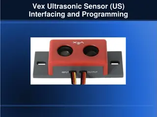
ULTRASOUND GENERATION Ultrasound is generated with a transducer. A piezoelectric element in the transducer converts electrical energy into mechanical vibrations (sound), and vice versa. Quartz and some other crystal have a lattice structure such that if a plate is cut out of the crystal with a certain orientation with respect to the crystallographic axis, and subjected it to an electric field in the right direction it will change its direction, it will contract or expands according to the polarity of the field. Conversely when a similar deformation of the plate is brought about by an external mechanical force, electric charges appear on its opposite surfaces. The transducer is capable of both transmitting and receiving sound energy.
TYPES OF PROBES Normal Beam Transducers Angle Beam Transducers Angle beam transducers are single element transducers used with a wedge to introduce a refracted shear wave or longitudinal wave into a test piece.
PIEZOELECTRIC TRANSDUCERS PT s contain polarized material When electric charge is applied, dipoles are induced and dimensions change If a force is placed on the material, it will change dimensions and create an electric field
TEST TECHNIQUES Ultrasonic testing is a very versatile inspection method, and inspections can be accomplished in a number of different ways. Ultrasonic inspection techniques are commonly divided into three primary classifications. Pulse-echo and Through Transmission (Relates to whether reflected or transmitted energy is used) Normal Beam and Angle Beam (Relates to the angle that the sound energy enters the test article)
TEST TECHNIQUES - PULSE-ECHO In pulse-echo testing, a transducer sends out a pulse of energy and the same or a second transducer listens for reflected energy (an echo). Reflections occur due to the presence of discontinuities and the surfaces of the test article. The amount of reflected sound energy is displayed versus time, which provides the inspector information about the size and the location of features that reflect the sound. f initial pulse back surface echo crack echo crack 0 2 4 6 8 10 plate UT Instrument Screen
TEST TECHNIQUES PULSE-ECHO (cont.) Digital display showing signal generated from sound reflecting off back surface. Digital display showing the presence of a reflector midway through material, with lower amplitude back surface reflector. The pulse-echo technique allows testing when access to only one side of the material is possible, and it allows the location of reflectors to be precisely determined.
TEST TECHNIQUES THROUGH- TRANSMISSION Two opposing sides of the test specimen are used. One transducer acts as a transmitter, the other as a receiver. Discontinuities in the sound path will result in a partial or total loss of sound being transmitted and be indicated by a decrease in the received signal amplitude. Through transmission is useful in detecting discontinuities that are not good reflectors, and when signal strength is weak. It does not provide depth information. transducers located on 11 T R R T 2 11 2 0 2 4 6 8 10
Calculations: Length of cement block (l)= 150mm Time (t) = 38 s Velocity = l/t, v = 3.9km/sec. Velocity criteria for cement quality grading: SL.NO PLUSE VELOSITY (Km/SEC) QUALITY GRADE 1 >4.5 EXCELLENT 2 3.5-4.5 GOOD 3 3.0-3.5 MEDIUM 4 <3.0 DOUTFUL
TEST TECHNIQUES THROUGH- TRANSMISSION Digital showing received sound material thickness. display through Digital showing received signal due to presence of a discontinuity in the sound field. display loss of
TEST TECHNIQUES NORMAL AND ANGLE BEAM In normal beam testing, the sound beam is introduced into the test article at 90 degree to the surface. In angle beam testing, the sound beam is introduced into the test article at some angle other than 90. The choice between normal and angle beam inspection usually considerations: - the sound should be directed to produce the largest reflection from the feature. - obstructions on the surface of the part that must be worked around. depends on two
DATA PRESENTATION Ultrasonic data can be collected and displayed in a number of different formats The three most common formats are known in the NDT world as 1. A-scan presentation 2. B-scan presentation 3. C-scan presentation Each presentation mode provides a different way of looking at and evaluating the region of material being inspected
A-SCAN PRESENTATION The A-scan presentation displays the amount of received ultrasonic energy as a function of time. The relative amount of received energy is plotted along the vertical axis and the elapsed time (which may be related to the sound energy travel time within the material) is displayed along the horizontal axis
B-SCAN PRESENTATION The B-scan presentations is a profile (cross-sectional) view of the test specimen. In the B-scan, the time-of-flight (travel time) of the sound energy is displayed along the vertical axis and the linear position of the transducer is displayed along the horizontal axis.
C-SCAN REPRESENTATION The C-scan presentation provides a plan-type view of the location and size of test specimen features. The plane of the image is parallel to the scan pattern of the transducer. C- scan presentations are produced with an automated data acquisition system, such as a computer controlled immersion scanning system. The C-scan presentation provides an image of the features that reflect and scatter the sound within and on the surfaces of the test piece.
INSPECTION APPLICATIONS Some of the applications for which ultrasonic testing may be employed include: Flaw detection (cracks, inclusions, porosity, etc.) Erosion & corrosion thickness gauging Assessment of bond integrity in adhesively joined and brazed components Estimation of void content in composites and plastics Measurement of case hardening depth in steels Estimation of grain size in metals
THICKNESS GAUGING Ultrasonic thickness gauging is routinely utilized petrochemical industries to determine various degrees of corrosion/erosion. Applications piping systems, storage and containment facilities, and pressure vessels. include in the and utility
FLAW DETECTION Contact, pulse-echo inspection for delaminations on 36 rolled beam. Signal showing multiple back surface echoes in an unflawed area. Additional echoes indicate delaminations in the member.
FLAW DETECTION IN WELDS One of the most widely used methods of weldment inspection. Full penetration welds lend readily to angle beam shear wave examination. inspecting ultrasonic is groove themselves
APPLICATIONS Inspection of rails for bolts holes breaks without dismantling end assemblies Inspection of moving strip or plate (for laminations) as regards its thickness Routine inspection of locomotive axels and wheels pins for fatigue cracks
ULTRASONIC TESTING IN THE FOUNDRY INDUSTRY Inspection of large castings and forging, for internal soundness before carrying out expensive machining operations. These include Voids, porosity, inclusions and cracks good area of casting porosity indication
WELDMENTS (WELDED JOINTS) The most commonly occurring defects in welded joints are Porosity Slag inclusions Lack of side-wall fusion Lack of inter-run fusion Lack of root penetration Undercutting, and Longitudinal or transverse cracks
Miscellaneous Ultrasonic Applications Ice measurement of ice thickness on ponds and lakes, studies of ice buildup in coolers and other industrial processes Concrete monitor mechanical properties such as compressive strength
Medical and Biological Research Applications These have included thickness measurements of skin layers, muscle and fat, and corneal tissue, as well as sound velocity measurements that can be related to the integrity of bone Wood Products Verifying bonding in laminated plywood and particle board, and measurement of elastic properties. Minerals, Rocks, Sand, Soil ultrasonic properties to measure physical parameters such as hardness, elasticity, and grain structure, as well as compaction of soil or sand under laboratory conditions
Advantage of Ultrasonic Testing Sensitive to small discontinuities both surface and subsurface. Depth of penetration for flaw detection or measurement is superior to other methods. Only single-sided access is needed when pulse-echo technique is used. High accuracy in determining reflector position and estimating size and shape. Minimal part preparation required. Electronic equipment provides instantaneous results. Detailed images can be produced with automated systems. Has other uses such as thickness measurements, in addition to flaw detection.
LIMITATIONS OF ULTRASONIC TESTING Surface must be accessible to transmit ultrasound. Skill and training is more extensive than with some other methods. Normally requires a coupling medium to promote transfer of sound energy into test specimen. Materials that are rough, irregular in shape, very small, exceptionally thin or not homogeneous are difficult to inspect. Cast iron and other coarse grained materials are difficult to inspect due to low sound transmission and high signal noise. Linear defects oriented parallel to the sound beam may go undetected. Reference standards are required for both equipment calibration, and characterization of flaws.


")


")