Understanding the Arduino Board for Embedded Programming and Robotics

Explore the key features of the Arduino board, including its open-source design, types such as Uno and Mega, essential components like power sources and I/O pins, notes on usability, and the concept of Arduino Shields. Learn how to use a breadboard for connecting devices in robotics projects effectively.

Download Presentation

Please find below an Image/Link to download the presentation.
The content on the website is provided AS IS for your information and personal use only. It may not be sold, licensed, or shared on other websites without obtaining consent from the author. Download presentation by click this link. If you encounter any issues during the download, it is possible that the publisher has removed the file from their server.
E N D
Presentation Transcript
Embedded Programming and Robotics Lesson 3 The Arduino Board The Arduino Board 1
The Arduino This board is an open-source project designed to teach digital electronics That is, anyone can build an Arduino board It was designed in Ivrea, Italy in 2005 by Massimo Banzi & David Cuartielles Uses an Atmel processor The Arduino Board 2
Types of Arduino Uno The most common, cheapest board, suitable for most applications. 12 digital I/O pins (some of this handle PWM, discussed later) 6 analog inputs 3.3V power 5V power Ground This is what we ll use The Arduino Board 3
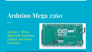
Types of Arduino Mega Much more powerful Faster processor More memory More I/O pins Takes more power to run More expensive Less suitable for what we re doing, since size and power are important for a robot The Arduino Board 4
PWR IN USB (to Computer) RESET SCL\SDA (I2C Bus) POWER 5V / 3.3V / GND Digital I\O PWM(3, 5, 6, 9, 10, 11) Analog INPUTS The Arduino Board 5
Notes on Arduino The USB connector can supply power, or you can use an external source, which we will use for the robot. The board has a voltage regulator. The reset button will restart the current program Programs don t go away when you turn the power off The Arduino Board 6
Arduino Shields This is a term you ll see in most things that talk about this board It means a board that plugs into the I/O pins and covers the Arduino You can (usually) stack multiple shields We won t be using shields in this workshop; we ll go straight to the hardware The Arduino Board 7
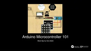
Using the Breadboard All devices will be mounted on the breadboard, not connected directly to the Arduino This will allow you to change things easily as we add new devices to your robot The Arduino Board 8
Using the Breadboard Connect the rails on the breadboard: +5 from the Arduino to + on the breadboard, using a male-to-male jumper Ground from the Arduino to on the breadboard When you add a device, plug it into the breadboard Run control signals from the Arduino to the appropriate holes on the breadboard The Arduino Board 9
Blinking an LED We built a circuit to turn on an LED Now let s put it under computer control Basic methodology: 1. Turn LED on 2. Wait 3. Turn LED off 4. Wait 5. Go back to step 1 The Arduino Board 10
Blinking an LED Hardware Setup Connect the LED as shown in the photo below. Note that the 330 resistor is in series with pin 2 and the long pin of the LED This is to limit the current and prevent the LED from burning out The short pin of the LED is connected to ground The Arduino Board 11
Writing the Code Decide which pin you ll attach the LED to; I suggest pin 2, on the lower right in the diagram Initialize the pin for output In the loop: Set the pin high Wait 1 second (1000 milliseconds) Set the pin low Wait 1 second Repeat The Arduino Board 12
Running the Program Connect the Arduino to your PC with the USB cable Wait until the PC acknowledges that it s connected Click the right arrow button to upload The LED should blink, one second on, one second off This One The Arduino Board 13
Whats Going On? The program will run as long as the board has power Disconnect the USB cable from the computer The LED goes dark Reconnect the USB cable The program starts running The program is stored in non-volatile memory Only the variables are in volatile memory The Arduino Board 14
Blinking Two LEDs You can use another pin to blink a second LED You ll need another 330-Ohm resistor Write the code to blink the first LED for a second, turn it off for a second, then blink the second one for a second, and turn it off for a second The Arduino Board 15
Writing a Function You can write a function to blink any LED Take the code you wrote for blinking a specific LED and make the pin number a parameter Good coding practice, as you have seen, uses constants rather than literals for the numbers The Arduino Board 16
Digital Sensors Overview Many sensors are, in effect, switches, in that they are either on or off: motion was detected or not, the door is open or closed, etc. We ll talk about analog sensors later The Arduino Board 17
Basic Digital Sensor Circuit Note that the Arduino pin is not in series with +5, the switch, and ground When the switch is closed, a small amount of current flows from +5 to ground and also to the input pin 2, which is also a ground How much current? By Ohm s Law, I=V/R, 5/10000 = .0005 amperes to Digital Pin 2 The Arduino Board 18
Delayed Reaction Normally, you flip a switch and something happens immediately When the light (output) is isolated from the input (switch), you can do interesting things Modify the program to wait for two seconds after the switch is pressed to turn off the light (this might give you time to leave the room, for example) The Arduino Board 19
Analog Input We can read a light sensor, which allows more voltage to flow with more light and less when it s dark Write a program that causes the LED to shine more brightly when the values from the LDR are lower, and less when they re higher We ll cover this in detail later The Arduino Board 20
Analog Input With the 18K resistor, light values range from about 800 in bright light to 10 or so in near-complete darkness. Write a program that causes the LED to shine more brightly when the values from the LDR are lower, and less when they re higher Remember that you can use the serial monitor to see the values The Arduino Board 21