Understanding Arduino Timer and External Interrupts

Interrupts play a crucial role in Arduino programming, allowing for immediate responses to external events. This content covers the concepts of timer interrupts and external interrupts, their applications, and how to use them effectively in Arduino projects. It explains how interrupts work, provides examples of implementing timer interrupts for precise timing tasks and external interrupts for responding to external events such as button presses, and guides you on how to set up and manage interrupts in your Arduino programs.

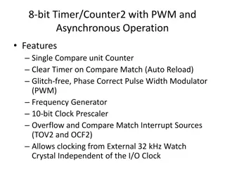
Download Presentation

Please find below an Image/Link to download the presentation.
The content on the website is provided AS IS for your information and personal use only. It may not be sold, licensed, or shared on other websites without obtaining consent from the author. Download presentation by click this link. If you encounter any issues during the download, it is possible that the publisher has removed the file from their server.
E N D
Presentation Transcript
Stem 5 Arduino timer interrupt and external interrupt KH Wong Stem4: Arduino and Computer vision, v.0.b2 1
Overview What is interrupt. How to use timer interrupt? Test5.1 How to use external interrupt? Stem4: Arduino and Computer vision, v.0.b2 2
What is interrupt? Main () { : Doing something (e.g. browsing) : } Phone rings activate interrupt Can happen anytime Depends on types of interrupts Phone rings _isr() //Interrupt service routine { some tasks (e.g. answer telephone) Phone rings }//when finished, //goes back to main Timer interrupt: you may set up a timer to activate interrupt External interrupt: you may use an external pin to activate interrupt when the external pin changes state. 3 CEG2400 12SWI, and 14. init V7a
Application examples Regularly reading a sensor, or blinking an LED. Since the timer frequency is fixed, it is more accurate than blinking an LED by a time delay method. Timer interrupt: Timer interrupts the CPU at a rate of 1KHz. At each interrupt an timer interrupt service routine (timer_isr) will run to change the state of an LED. When your computer is running, a key press will trigger an interrupt to input a character to your system External interrupt: When a key is pressed (the key is attached to an external pin, so its state will change) an interrupt service routine (ext_isr) will be executed to read the keyboard. 4 CEG2400 12SWI, and 14. init V7a
TEst5.1 Blink LEDs at different frequencies. // https://www.instructables.com/id/Arduino-Timer-Interrupts/ //this enables all three Arduino timer interrupts. //timer0 will interrupt at 2kHz, blinking an LED at pin8 at 1KHz //timer1 will interrupt at 1Hz, blinking an LED at pin13 at 0.5Hz //timer2 will interrupt at 8kHz, blinking an LED at pin9 at 4KHz Stem4: Arduino and Computer vision, v.0.b2 5
//set timer1 interrupt at 1Hz TCCR1A = 0;// set entire TCCR1A register to 0 TCCR1B = 0;// same for TCCR1B TCNT1 = 0;//initialize counter value to 0 // set compare match register for 1hz increments OCR1A = 15624;// = (16*10^6) / (1*1024) - 1 (must be <65536) // turn on CTC mode TCCR1B |= (1 << WGM12); // Set CS12 and CS10 bits for 1024 prescaler TCCR1B |= (1 << CS12) | (1 << CS10); // enable timer compare interrupt TIMSK1 |= (1 << OCIE1A); Setup test5.1.ino //https://www.instructables.com/id/Arduino-Timer-Interrupts/ //this code will enable all three arduino timer interrupts. //timer0 will interrupt at 2kHz, blinking an LED at pin8 at 1KHz //timer1 will interrupt at 1Hz, blinking an LED at pin13 at 0.5Hz //timer2 will interrupt at 8kHz, blinking an LED at pin9 at 4KHz //storage variables boolean toggle0 = 0;boolean toggle1 = 0;boolean toggle2 = 0; void setup(){ //set pins as outputs pinMode(8, OUTPUT); pinMode(9, OUTPUT); pinMode(13, OUTPUT); //set timer2 interrupt at 8kHz TCCR2A = 0;// set entire TCCR2A register to 0 TCCR2B = 0;// same for TCCR2B TCNT2 = 0;//initialize counter value to 0 // set compare match register for 8khz increments OCR2A = 249;// = (16*10^6) / (8000*8) - 1 (must be <256) // turn on CTC mode TCCR2A |= (1 << WGM21); // Set CS21 bit for 8 prescaler TCCR2B |= (1 << CS21); // enable timer compare interrupt TIMSK2 |= (1 << OCIE2A); sei();//allow interrupts }//end setup cli();//stop interrupts //set timer0 interrupt at 2kHz TCCR0A = 0;// set entire TCCR2A register to 0 TCCR0B = 0;// same for TCCR2B TCNT0 = 0;//initialize counter value to 0 // set compare match register for 2khz increments OCR0A = 124;// = (16*10^6) / (2000*64) - 1 (must be <256) // turn on CTC mode TCCR0A |= (1 << WGM01); // Set CS01 and CS00 bits for 64 prescaler TCCR0B |= (1 << CS01) | (1 << CS00); // enable timer compare interrupt TIMSK0 |= (1 << OCIE0A); Stem4: Arduino and Computer vision, v.0.b2 6
ISR Interrupt service routines of test5.1.ino ISR(TIMER0_COMPA_vect){//timer0 interrupt //2kHz toggles pin8 //generates pulse wave of frequency 2kHz/2 = 1kHz // (takes 2 cycles for full wave- toggle high then low) if (toggle0){ digitalWrite(8,HIGH); toggle0 = 0; } else{ digitalWrite(8,LOW); toggle0 = 1; } } ISR(TIMER1_COMPA_vect){//timer1 inter.1Hz toggles p13 //generates pulse wave of frequency 1Hz/2 = 0.5kHz // (takes 2 cycles for full wave- toggle high then low) if (toggle1){ digitalWrite(13,HIGH); toggle1 = 0; } else{ digitalWrite(13,LOW); toggle1 = 1; } } ISR(TIMER2_COMPA_vect){ //timer1 interrupt 8kHz toggles p9 //generates pulse wave of //frequency 8kHz/2 = 4kHz // (takes two cycles for full //wave-toggle high //then toggle low) if (toggle2){ digitalWrite(9,HIGH); toggle2 = 0; } else{ digitalWrite(9,LOW); toggle2 = 1; } } void loop(){ //do other things here } Stem4: Arduino and Computer vision, v.0.b2 7
Test5.1 code (full code) https://www.instructables.com/id/Arduino-Timer-Interrupts/ Test 5.1: Timer interrupt //timer interrupts //by Amanda Ghassaei //June 2012 //https://www.instructables.com/id/Arduino-Timer-Interrupts/ // /* * This program is free software; you can redistribute it and/or modify * it under the terms of the GNU General Public License as published by * the Free Software Foundation; either version 3 of the License, or * (at your option) any later version. * */ //timer setup for timer0, timer1, and timer2. //For arduino uno or any board with ATMEL 328/168.. diecimila, duemilanove, lilypad, nano, mini... //https://www.instructables.com/id/Arduino-Timer-Interrupts/ //this code will enable all three arduino timer interrupts. //timer0 will interrupt at 2kHz, blinking an LED at pin8 at 1KHz //timer1 will interrupt at 1Hz, blinking an LED at pin13 at 0.5Hz //timer2 will interrupt at 8kHz, blinking an LED at pin9 at 4KHz //storage variables boolean toggle0 = 0; Stem4: Arduino and Computer vision, v.0.b2 8 boolean toggle1 = 0; boolean toggle2 = 0;
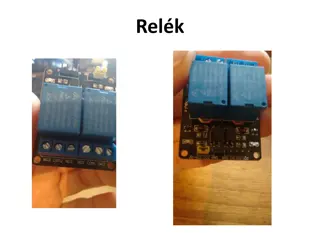
Test 5.2 External interrupt test Interrupt arises whenever the normal flow of a program has to be halted temporarily to another routine. For example to serve an interrupt (IRQ) for a hardware key press input The LED will toggle (change state: from high to low, or low to high) when the push button is depressed once. Arduino Computer 9 CEG2400 12SWI, and 14. init V7a
Test5.2 external interrupt code https://www.allaboutcircuits.com/technical-articles/using-interrupts-on-arduino/ The resistor (10K) and capacitor (10uF) attached to the push button are used to minimize the denounce problem void loop() { // Nothing here! while (1) { Serial.println( Main loop1"); delay(1000); Serial.println( Main loop2"); delay(1000); } } void pin_ISR() { buttonState = !buttonState; digitalWrite(ledPin, buttonState); Serial.println("INTERRUPTED"); Serial.println(buttonState); } const int buttonPin = 2; const int ledPin = 13; int buttonState = 0; void setup() { Serial.begin(9600); pinMode(ledPin, OUTPUT); // init input pin: pinMode(buttonPin, INPUT); //interrupt ISR vector attachInterrupt(0, pin_ISR, CHANGE); } The 100 Ohm resistor is used to limit current flow Stem4: Arduino and Computer vision, v.0.b2 10
Test 5.2 External interrupt Full code // Pull up resistor //pin2 ----------10k Ohm--->5V // | | // 10uF--- / on-off sw1 // --- | // | | // GND GND // //Pin 13 ---100 Ohm -->|--GND // LED // // variables will change: const int buttonPin = 2; // the number of the pushbutton pin const int ledPin = 13; // the number of the LED pin // variables will change: //volatile int buttonState = 0; // variable for reading the pushbutton status int buttonState = 0; // variable for reading the pushbutton status void setup() { Serial.begin(9600); // initialize the LED pin as an output: pinMode(ledPin, OUTPUT); Stem4: Arduino and Computer vision, v.0.b2 11 // initialize the pushbutton pin as an input: pinMode(buttonPin, INPUT);


")