RF Leakage Investigations & Atomic Clock Signal Phase Drift Analysis

RF signals ranging from 100 kHz to 150 MHz are utilized for achieving resonance in optical cavities. DC Ground Isolation Units help decouple DC grounds and shield leakage. Spectrum analysis using RF analyzers reveals peaks possibly from neighboring balun leakages. Solutions involve increasing capacitance to reduce RF leakage. Future plans include testing modifications to baluns and assessing their impact on the IFO's performance. Atomic clock phase drift affects long integration time measurements, highlighting the importance of signal stability.

Download Presentation

Please find below an Image/Link to download the presentation.
The content on the website is provided AS IS for your information and personal use only. It may not be sold, licensed, or shared on other websites without obtaining consent from the author. Download presentation by click this link. If you encounter any issues during the download, it is possible that the publisher has removed the file from their server.
E N D
Presentation Transcript
RF Leakage Investigations & Atomic Clock Signal Phase Drift Analysis John Schaefer Mentor: Dick Gustafson
RF Signals and the IFO LIGO Radio Frequency (RF) roughly ranges from 100 kHz to 150 MHz RF signals used to derive control signals for achieving resonance in our optical cavities Tells cavities whether they re too short or too long and steers changes in cavity length accordingly RF leakages can contaminate signals in other electronics Suspected to be a reason behind some losses of lock and source of noise
DC Ground Isolation Units (Baluns) Decouples DC grounds using a transformer and shields leakage with enclosure RF leakages observed when measuring ground to ground across the balun Largest leakage seen on balun mounted on PSL electronics rack with -22 dBV (~79 mVrms) at 80 MHz
Typical Spectrum Analysis using RF Analyser Measured from cabling ground to cabling ground across balun This balun transmits a 35.5 MHz current -29 dBV is about 35 mVrms Other peaks are suspected to be due to leakages from neighboring baluns
Circuit Diagram & Solutions Solution: Increase capacitance! Recall that ? = Modifications: Replace cap with conductor (copper) Add more capacitors in parallel on the other cap Results: Peak goes from -22 dBV (~79 mVrms) to -50 dBV (~3.2 mVrms) at 80 MHz 1 ??? DCC: LIGO-D1101077-v1
Future Plans Improve and test further modifications to the baluns (i.e. add more capacitors?) Identify other baluns that are candidates for replacement Investigate big picture impact on IFO
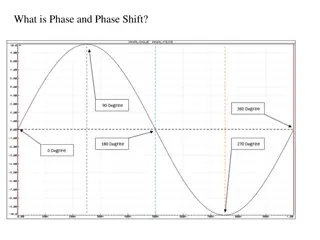
Atomic Clock Phase Drift We use an atomic clock as well as GPS for timing on the IFO When triggering a signal from a rubidium clock on a 1 PPS GPS signal, the signal seems to wander in phase Small phase shifts may not matter in small timescale measurements, but algorithms that use long integration times would see the effect i.e. Algorithms that perform continuous wave searches
Long Term Measurement of Horizontal Shift Mean drift of 213.55 ps per second We can likely tune the clock to get rid of linear drift
Test for Periodicity Creating periodogram we find the two most interesting peaks are 5.02 mHz (~200 s period) 1.205 mHz (~14 min period)
Future Plans Tune atomic clock to get rid of linear phase drift Investigate the sources of these periodicities Perform same analysis on an atomic clock more identical to the one use on H1 Take two identical RF Oscillator Sources and have one disciplined by GPS and the other by an atomic clock and analyze the difference


")