Managing E-Beam Drift for Semiconductor Fabrication
Explore techniques to address e-beam drift issues in semiconductor manufacturing, such as alignment using wafer marks and multi-pass writing strategies. Learn how to minimize drift problems and improve productivity in the fabrication process.
Uploaded on Sep 14, 2024 | 0 Views
Download Presentation

Please find below an Image/Link to download the presentation.
The content on the website is provided AS IS for your information and personal use only. It may not be sold, licensed, or shared on other websites without obtaining consent from the author. Download presentation by click this link. If you encounter any issues during the download, it is possible that the publisher has removed the file from their server.
E N D
Presentation Transcript
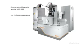
Living with e-beam drift Part 1: The e-beam is not broken Version 3 M. Rooks Yale University
Other ways to minimize drift problems 3. Alignment using marks on the wafer is a very good way to correct for drift, BUT you have to write patterns that can be exposed in just a few minutes. You should be writing many small chips so that the system will realign often. On the EBPG, one pattern file gets one alignment. So if you need n alignments then you need n patterns. If you have been forced to use gigantic patterns that take a long time to print, then (in theory) you would create a jobfile.ini that contains pg set calrealign 1 , which should inspire the EBPG to realign to the chip marks each minute. Unfortunately this does not work. It s a bug: calrealign will induce a one-point drift check, not a full chip alignment sequence. You can work around this bug by splitting your pattern into n smaller patterns. This can be done (the hard way) with Beamer or with the utility gpfsplit (the easy way). Later in this presentation you ll see an example of using gpfsplitto force realignments.
Living with e-beam drift Part 2: Multi-pass writing and sorting fields
You could try gpfsort v merged.gpf But the results are not so great. So let s try a different option.
Another Example: Random Walks How can you optimize a pattern which is so dense that Yellow Brick Road sorting is ambiguous? Here is an example of a pattern that cannot be properly reordered with the gpfsort options ybr, v, h, or ts. In this case we would like to specify the writing order manually, and we can, using the path option.
Another Example: Random Walks Simply create a text file called path.txt, and type in the vertices of the desired exposure path. These coordinates should be the ones seen in the gpf file (using cview) or they can have the same origin as the original CAD file. The path should follow the desired field centers, but the numbers do not have to be precise. This path defines the writing order, not the field placement.
Another Example: Random Walks path.txt lower-left -500 -600 upper-right 400 400 # -300 -70 -300 80 -150 80 -150 -70 0 -70 0 80 150 -70 300 -70 300 80 150 80 gpfsort path path_example.gpf It might be tedious to type in a long path, but you will get exactly what you want. Look at the example path.txt file for helpful hints. If you want to use the same origin as the original CAD, then you must specify lower-left and upper- right coordinates in path.txt
I swear this is the last example: multi-pass writing with realignment Suppose you have a long pattern with many writing fields, and that you have used Beamer (or whatever) to create three overlapping patterns, as we did ~11 slides ago. 600 m Overlapping patterns (written at 1/3 dose each) wash away stitching errors, but there will still be an overall curve in the pattern from one end to the other. This runout error is a serious problem for multi-level devices. Fortunately in this example you have first fabricated alignment marks in the corners. Remember each pattern file gets one alignment to the marks. If you simply do not merge together the three overlapping pattern files, then you can use cjob to align and expose three times.
but If the pattern takes (let s say) one hour to write,* then each 1/3 pattern takes 20 minutes. We really should realign more often than that. So let s merge and sort the pattern as before, but then split it into 12 parts so that the system will realign every five minutes. (Now click to start our lovely animation.) align align align align File 2 File 1 File 3 File 4 The sequence for setting up this exposure is * Yes of course thispattern would not take an hour to write, but let s pretend.
The sequence for setting this up: Generate the pattern by whatever means CAD or algorithmically Beamer generate three gpf files each with the same center but shifted lower-left corners let s call them wiggle1.gpf, wiggle2.gpf, wiggle3.gpf Merge the three gpf files together with gpfmerge wiggle*.gpf We should sort the fields with the ybr (default) or h option: gpfsort merged.gpf I don t like the resulting file name, so let s rename it: mv merged_sorted.gpf wiggle.gpf Split the file into 12 pieces with gpfsplit wiggle.gpf 12 Now we have ~ 12 gpf files with the names like wiggle_0.gpf and wiggle_12.gpf.
Finally You can view all of these gpf files at the same time with cview wiggle_*.gpf Cview will display the different files as different colors: Now you can use cjob to define the alignment marks, and to specify the exposure of all 12 patterns in the same place.
Use gpfsplit if you need a lot of realignments during exposure.
Living with e-beam drift Part 3: Dealing with drift inside a single field
We could apply the same drift checks used for multi-field patterns 1. If there are no alignment marks, then put pg set caldrift 00:01:00 into the jobfile.ini file. This will induce the system to measure a mark position (the one on the holder, by default) each minute. This will not work as well as you hope. 2. If you can fabricate alignment marks on the wafer AND if the pattern takes a long time to write, then a better technique is to split the pattern in to n parts, and then have the system realign n times. You can split the pattern by cropping sections with Beamer (in the extract module). Or you can use a smaller field size, then use gpfsplit to create n patterns. (Note that pg set calrealign 1 does not currently work.) Neither of these techniques will work very well. You really need to control the writing order, so read on.
What if your pattern is so dense that ybrsort cannot choose a sensible writing order? In that case you can use ybrsort to sort the shapes by a manually defined path (like gpfsort, but now sorting shapes inside each field.) Use the command ybrsort -path pathfile.txt pattern.gpf The pathfile.txt file contains points with the same origin as that of the original CAD, and you must specify the same lower-left and upper-right points you used to convert the pattern to gpf (in Beamer, most likely). The path might look like this: # a short path for ybrsort # lower-left -50 -60 upper-right 1000 57 -12 -34 0 0 56 78.2 100 78.2 jump 50 50 50 100
The path used for ybrsort can span many fields, and can be the same path used for gpfsort (field sorting). You might be thinking it would be very tedious to type in a long, complex path like this one. One trick for reducing the work is to draw the exposure path with your CAD program, using a path object on an unused layer. (A path in CAD is a segmented line of fixed width defined by a set of vertices. Look for this icon in the upper-left corner of Layout. After drawing the path by hand inside cell topcell on layer 45 (for example), you can extract it to a text file with the command extractpath cadfile.gds topcell 45 This creates the file extracted_path.txt, which you will have to edit to insert the lower-left and upper-right points.
Summary To compensate for drift inside a single field the best strategies are: 1. Let the wafer sit on the stage for many hours before writing, 2. Fabricate alignment marks on the wafer then split the pattern in to n parts, allowing the system realign n times. 3. For single waveguides use ybrsort to re-order the fields. If the pattern has radial symmetry, use radial_sort. To force an arbitrary order on your crazy pattern, use ybrsort path Find this and other e-beam presentations at nano.yale.edu


