DarkBox Setup and Testing Overview
This content provides an in-depth overview of the DarkBox setup and testing process conducted by V. Kulikovskiy and others in Napoli. It covers the setup finalization, software installation, extensive data acquisitions, challenges faced, and collaboration with external experts. The content showcases the meticulous testing and calibration procedures involved, including modifications, software development, and intense debugging efforts, all aimed at ensuring stable operation and optimal performance of the DarkBox system.

Download Presentation

Please find below an Image/Link to download the presentation.
The content on the website is provided AS IS for your information and personal use only. It may not be sold, licensed, or shared on other websites without obtaining consent from the author. Download presentation by click this link. If you encounter any issues during the download, it is possible that the publisher has removed the file from their server.
E N D
Presentation Transcript
Test boxes software and first tests V. Kulikovskiy
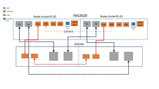
DarkBox Setup Equalised distance optical fiber splitter (C. Mollo) LASER 31 PMT 31 PMT BLACK BOX equal distance 20 kHz PMT base cables (M.Circela/Napoli) CLB II CLB I PC WRS
Software - DarkBox USB shells - LM32-2nd, WR V. van Beveren, CLBv2 group CLBSwissKnife C++, BOOST C. Pellegrino raw data acquisition tool DEBUG RemoteControl JAVA-App (V. van Beveren) low level CLB control ROYWebServer T. Gal rate visualizer Detector Manager (C. Bozza) High-level control via scripts, web-based technology, STABLE OPERATION DarkBoxAnalyzer C++,ROOT offline analysis (TT, ToT..) DarkBox Control JAVA-App (V. Kulikovskiy) launch scripts for DM, operate DataBase , PMT tests and analysis with 1 button click CLB firmware/software (CLBv2 group) modifications for PPS (VK) Intensive testing of all components together! Heavy debugging of the whole system. A lot of support (usage, bug fixing): NIKHEF (V. van Beveren, P. Jansweier ) IFIC (D. Calvo, D. Real C. Bozza, C. Pellegrino, T. Chiarusi, A. Orzelli Database PROMIS Default HV requests (wget) XML database output
Dark Box Setup CLB I with PPS signal modified (output is LEMO, signal is 20 KHz trigger, synchronized with PPS). V2.2 CLB I I V2.2 no modifications Laser Pilas Advanced Laser diodes White rabbit switch, SFP avago & comm fibers Extended cables for the PMT bases (Napoli) Calibrated Optical fibers to each PMT (equalized distance). During this week only one PMT + 1 fiber was used.
First DarkBox Calibration and Tests C. Mollo, G. Riccobene, V. Kulikovskiy 24-26 Nov., Napoli 3 tough and intense days in Napoli: Setup finalization (DarkBox is so dark!) Software installation (SL6, 1.5 hard days) ~100 different data acquisitions (PMT base cable reattached ~50 times) Excellent pizza + and lost flight to Catania External help of C. Pellegrino & C. Bozza!
ToT vs TT afterpulses
1 CLB drives laser, and reads PMTs The same channel evening/morning next day Laser + PMT to the same CLB delta T ~130+-25 ps difference between the same measurements
2 CLBs + WRS syncro CLB drives Laser and detects light with PMT at channel 0 One CLB drives Laser, second one detects light with PMT at channel 0 Hit time peak value difference is 120+-35 ps (from fit) delta t(ns)
Fixed latency: CLB I drivers Laser, CLB II reads PMT (ch 28) mean value gauss fit CLBs restart CLBs + WRS restart
delta T for all Octopus channels (same PMT and setup) Large-Small mean difference is 780 ps Max difference 1.4 ns different path length? LARGE SMALL 111.157+-0.004 110.374+-0.004
Added measurements with other CLB + other octopuses (no laser attached to it) Scope test CLB + Octopus channels (to be completed) The difference in delta t are smaller than 200 ps synchronization (for each channel measurement CLBs are switched OFF)? or real difference ? negligible LARGE SMALL PMT+Laser+CLB I Laser+CLB I, PMT + CLB II
HV tuning Hamamtsu provides the Nominal High Voltage obtained in Current mode operation ad for 2:1:1 dynode ratio. KM3Net works in pulsed mode and at 3:1:1 Tune HV : TOT 26.4 (reference by Oleg K. average value og 600 PMT) Scan HV from Hamamatsu NHV -100 V; +50 V with a step 25 V Base Threshold 1094 mV (2F) 0.3 p.e.
HV tuning Hamamtsu provides the Nominal High Voltage obtained in Current mode operation ad for 2:1:1 dynode ratio. KM3Net works in pulsed mode and at 3:1:1 Tune HV : TOT 26.4 (reference by Oleg K. average value og 600 PMT) Scan HV from Hamamatsu NHV -100 V; +50 V with a step 25 V Base Threshold 1094 mV (2F) 0.3 p.e. error is gaus sigma Hamatsu Nominal HV HV tuned
TT dependence from HV 70 ns (Carlos previous measuremetns) 110 ns ->71.3 ns measured TT peak -87.9 ns optical path delay +49 ns trigger anticipation before PPS
Software GreenBox (to develop) USB shells - LM32-2nd, WR V. van Beveren, CLBv2 group DEBUG CLBSwissKnife C++, BOOST C. Pellegrino raw data acquisition tool RemoteControl JAVA-App (V. van Beveren) low level CLB control ROYWebServer T. Gal rate visualizer Detector Manager (C. Bozza) High-level control via scripts, web-based technology, STABLE OPERATION GreenBoxAnalyzer C++,ROOT offline analysis GreenBox Control JAVA-App (V. Kulikovskiy) Rotation of the DOM AHRS data output Piezo control LED beacon contrlol Setup creation (Bologna?) XML database output CLB firmware/software (CLBv2 group) modifications for AHRS operations (VK)
Conclusions DarkBox has a great mechanical realization darkrate << 1 kHz easy to operate fast test of 62 PMTs is proven to be possible and fast it already unique measurements of the channel delays already GreenBox Mechanical realization of 2 boxes is ready Almost all the software can be reused from the official ones for the future detector


")


")